How it works
A detailed technical account of the Jetspray, put together from the patent, the company's brochures and service leaflet, Bob Ruth's handwritten shop notes, the Robbins & Myers pump manual and the family's photographs. Every number below gives its source, and anything that is our estimate is labelled as one.
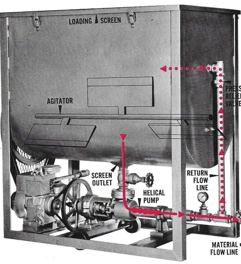
Overview & material path
The problem. The patent describes how cement-based roof coatings were usually applied in the early 1960s: a crew mixed the material on the ground, loaded it into bucket elevators, hauled it up to the roof, and two or more men spread it with swabs and buckets. Alex Jutila's aim, in the patent's words, was a mechanism with which "one man can perform an entire roof coating operation."
The answer. The Jetspray was one self-contained unit: a gasoline engine, a mixing tank with a slowly turning agitator, a positive-displacement pump and a single long hose. The coating stayed mixed in the tank, was pumped up to the roof, and was sprayed without compressed air (hence "airless"). Anything the hose didn't take went back into the tank through a spring-loaded relief valve, so the pump could run against a closed gun without damage.
Scroll sideways to see the whole diagram →
- 1U-trough tank, 125–130 gal, hinged lid over an expanded-metal loading screen
- 2Paddle agitator on a 1 in shaft; rubber wipers sweep the bottom
- 3Screened outlet at the bottom centre (removable screen)
- 41-1/2 in 45° street ell, no-hub coupling, companion flange
- 5Moyno progressing-cavity pump (Robbins & Myers L3 frame)
- 6Discharge reducer, tapped 1/4 in pipe for the pressure gauge
- 71 × 3/4 × 3/4 in tee: flow splits here
- 83/4 in lever ball valve: the main shut-off to the hose
- 9Hose: 150 ft of 3/4 in Buna-N-lined in later sales literature (50 ft of 1/2 in in 1966)
- 10Spring-closed grip gun on a rigid wand, stainless fan nozzle
- 113/4 × 18 in riser with a union (upper and lower assemblies)
- 12Home-made spring-and-ball relief valve
- 13Return through the tank end wall, 3/4 in elbow pointing down
The power path
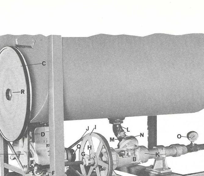
One engine drives everything through two V-belts. A V-Plex friction clutch on the engine shaft slips at idle and grips as the governor speeds the engine up. Its belt (J) turns the 12 in pump pulley (I) on a short jack shaft (G), which turns the pump through a Gerbing G-100 jaw coupling with a rubber spider. Bob Ruth's notes and the leaflet call it a "universal coupling" (H). A small pulley on the outer end of the jack shaft drives a second belt (D) up to the 18 in pressed-steel pulley (C) on the agitator shaft. The patent describes the same arrangement: pulleys 42 and 44 on drive shaft 13, with belt 45 going to pulley 47 on the agitator shaft.
Scroll sideways to see the whole diagram →
Open the full 3D model → The animation follows the same path: tank, pump, tee, hose and by-pass.
The patent
U.S. Patent 3,203,631, "Abrasive Type Roof Coating Apparatus." Alex O. Jutila, 5062 Zion, San Diego. Filed May 18, 1964 (Ser. No. 368,155) and issued August 31, 1965, with 3 claims in class 239-124. The attorneys were Hansen and Lane and the primary examiner was Everett W. Kirby. Download the patent (PDF).
The patent covers the problem of abrasive, cementitious coatings: mixtures of liquid with Portland cement or similar aggregate, applied over gravel roofs or mineral-surfaced cap sheet. If such a mixture is left still, the heavy particles settle out. If it is pumped, they pack into the outlet and choke it. The patent's answer is a set of parts that work together. That is typical of mechanical patents of the period: the individual parts (tanks, paddle agitators, helical pumps, by-pass valves) were already known, and what the claims protect is the combination.
What the three claims cover, in plain English
All three claims describe a "single line applicator" with these features in common:
- a tank with a cylindrical (half-round) bottom, with an agitator turning on the axis of that half-round;
- a flexible wiper blade on the agitator that reaches out and actually touches the curved bottom;
- a discharge line from the bottom of the tank, placed in the path of the wiper, with a grating over its inlet that the wiper sweeps on every turn;
- a pump fed from that line, with one power source driving both the pump and the agitator;
- one hose long enough to reach every part of the roof, ending in a nozzle with a valve to control it;
- a spring-biased valve that sets the pressure at which material flows from the pump to the nozzle.
Claim 1 is the most specific. It calls for several agitator blades, each set slightly clear of the bottom and each carrying its own wiper. It also requires that the spring valve sit in a by-pass line next to the pump discharge that returns material to the tank. Claim 2 is broader. It needs only a single wiper and "spring biased valve means" for controlling pressure, without describing the by-pass. Claim 3 adds the perforated shelf at the top of the tank, which receives and supports a bag of abrasive while it is slit open and emptied into the liquid.
What was actually new. Our reading is that the key idea is the wiper. Because the agitator is centred on the half-round bottom, a rubber edge on each blade can sweep the whole floor of the tank and pass straight across the outlet grating on every revolution. The patent says the wipers keep "the discharging grating 19 free from an accumulation of the aggregate particles." The examiner's citations include two mixers with scraper blades (Kacena's plaster mixer and Pro's mixer/conveyor) and sprayers with by-pass returns. That fits the idea that the claims were allowed for the combination of these features in a one-man, one-hose machine.
The six figures
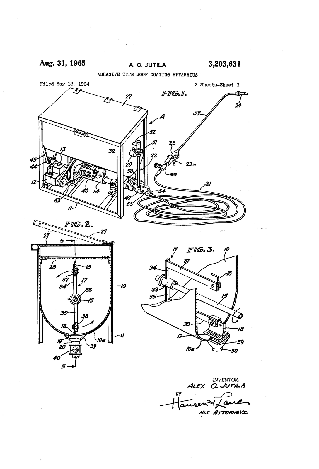
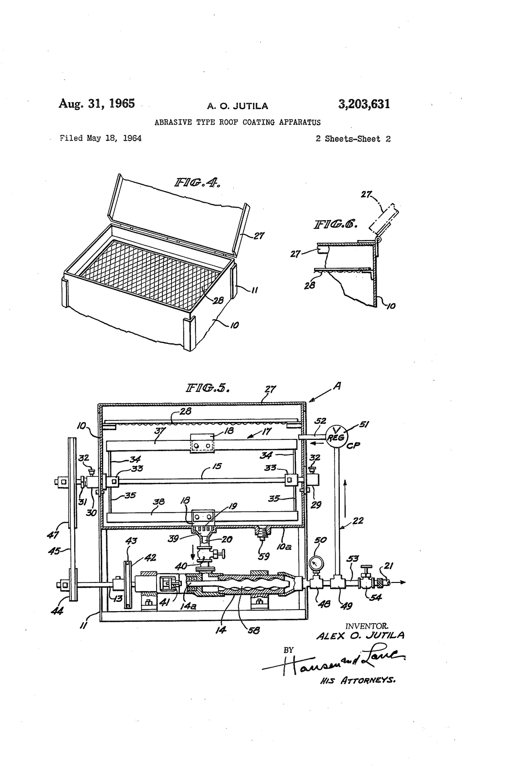
Reference numerals
From the patent text. The right-hand column is our best match to the production machine, using the service leaflet's letter callouts and Bob Ruth's notes.
| No. | Patent part | On the production machine |
|---|---|---|
| A | The apparatus as a whole | Airless Jetspray |
| 10 | Tank (10a: semi-cylindrical bottom) | Welded U-trough with half-round bottom |
| 11 | Castered base frame | Angle-iron cage; no casters visible in the leaflet photographs |
| 12 | Small gasoline engine | Briggs & Stratton, 4 HP (1966–67) / 5 HP (later) (E) |
| 13 | Drive shaft, coupled co-axially to the pump | 3/4 in jack shaft (G) and jaw coupling (H) |
| 14, 14a | Helical rotor pump with resilient housing; pump shaft | Robbins & Myers Moyno, L3 frame (K) |
| 15 | Agitator shaft | 1 in stub shafts, 12 in (pulley side) and 10 in |
| 17 | Paddle-type agitator | Centre blade plus two pitched outer blades (V) |
| 18 | Resilient wiper plates, rubber or neoprene, about 1/4 in thick | Rubber wipers on 10-24 stove bolts |
| 19 | Grating over the discharge | 9 × 9 outlet screen in the reducer bushing; three sizes supplied |
| 20 | Discharge line from the tank | 1-1/2 in street ell, no-hub coupling, companion flange (L, M, N) |
| 21 | High-pressure hose | 50 ft × 1/2 in (1966) or 150 ft × 3/4 in (later) |
| 22 | Pressure-controlled by-pass line | 3/4 in riser (P; parts 34–36) |
| 23, 23a | Spring-biased grip-actuated control valve; hand lever | Spray gun |
| 24 | Discharge nozzle (patent prefers a cone-shaped spray) | Stainless fan nozzle; four sizes supplied (later brochure) |
| 27 | Hinged cover | Hinged lid with draw latches |
| 28 | Perforate shelf (expanded metal), strong enough for an 80 lb bag dropped about a foot | Loading screen |
| 29 | Sealed cup-shaped bearing | Fafnir RCJC 1 in flange ball bearings, "NO SUBSTITUTE" (Bob Ruth's notes); a later mailer says "Oilite" bearings |
| 30, 31 | Bearing with packing gland | |
| 32 | Grease cups | Grease fittings, facing up |
| 33 | Hub members on the agitator shaft | Agitator end sleeves, pinned 1/4 in |
| 34, 35 | Diametrically opposed arms | Agitator arms |
| 37, 38 | Paddle blades | Agitator blades |
| 39 | Funnel-shaped entrance to the discharge line | Outlet bushing |
| 40 | Shut-off cock under the tank | Hand-wheel valve in the brochure cutaway; absent from the leaflet |
| 41 | Pump packing gland | Moyno L3 packing gland |
| 42 | Grooved pulley on drive shaft 13 | 12 in pump pulley (I) |
| 43 | V-belt from the engine | Pump drive belt (J) |
| 44 | Pulley on the outer end of drive shaft 13 | 1-3/4 in TRU-RUN pulley on the jack shaft |
| 45 | V-belt to the agitator | Agitator belt (D) |
| 47 | Pulley on agitator shaft 15 | 18 in pulley (C) |
| 48 | Pipe from the pump outlet | 1-1/4 × 1 in bushing, 1 × 4-1/2 in nipple |
| 49 | T-fitting | 1 × 3/4 × 3/4 in tee (38) |
| 50 | Pressure gauge | Gauge (O) |
| 51 | Pressure regulator valve | Home-made ball relief valve (S) |
| 52 | Return pipe into the tank | 3/4 in nipple, gaskets, 90° elbow (29–32) |
| 53 | Pipe from tee to hose | 3/4 in close nipple |
| 54, 55 | Shut-off cocks at each end of the hose | Outlet ball valve (X / 37) at the machine |
| 57 | Rigid tube (wand) | Wand |
| 58 | Pump impeller (rotor) | Moyno single-helix rotor |
| 59 | Drain outlet | Not identified in the production documents |
The 1964 prototype vs. the production machine
| Feature | Patent (filed 1964) | Production |
|---|---|---|
| Tank | Rectangular box with a semi-cylindrical bottom, about as tall as it is long (FIG. 1, 4, 5) | Long U-trough with a semicircular bottom in a full-height angle-iron cage |
| Capacity | "60 to 75 gallons" | 130 gal (1966–67 pieces) / 125 gal (later) |
| Base | "Castered base frame" | Angle-iron frame on base slats; no wheels visible |
| Agitator | Two opposed paddle blades on paired arms, one wiper each | Centre blade over the outlet plus two outer blades bent the opposite way, all with wipers and wire screens |
| Agitator bearings | Sealed cup bearing one end; packing-gland bearing the other; grease cups | Fafnir RCJC 1 in four-bolt flange bearings with grease fittings and copper-washer seals |
| Tank outlet | Funnel entrance, grating, shut-off cock 40 | Screened reducer bushing, 45° street ell, no-hub coupling; no cock in the leaflet |
| Pressure control | "Pressure regulator valve" 51, not detailed | Shop-built 7/8 in ball and spring valve on an 18 in riser |
| Hose valves | Shut-off cocks at both ends of the hose plus grip valve | Ball valve at the machine plus gun |
| Nozzle | Cone-shaped spray preferred | Stainless fan-spray nozzle |
Tank & agitator
The production tank is a long open trough. Its end plates are a "U" or "D" shape: straight sides at the top that blend into a semicircular bottom, with a curved weld seam visible in the shop Polaroids. The top edge is folded into a lip, and the leg braces are riveted through that lip with 1/4 in rivets, heads inside and tails "mushroomed" with a mallet (Bob Ruth's notes p. 11; instructions p. 9). A flat lid with turned-down edges hinges along the back and closes with two draw latches.
The agitator turns on the centreline of the half-round, so every blade passes the same distance from the curved floor. That geometry is what lets the wipers work.
Capacity check
Taking the reconstruction's derived tank (26.5 in wide, a 13.25 in radius bottom, 14 in of straight side above the shaft centre, 44 in long) and comparing it with the brochures:
The tank length (44 in) and width are derived from the 54 × 29 in brochure envelope. The close match with the advertised capacity is a check on the reconstruction, not an independent measurement.
The agitator, as Bob Ruth built it
- Blades. A long welded bar with a centre blade that is positioned "down over OUTLET hole" and two outside blades on the opposite side. The outside blades are bent "leading edge first (left down, right up)", so they are pitched (instructions p. 8; notes p. 9).
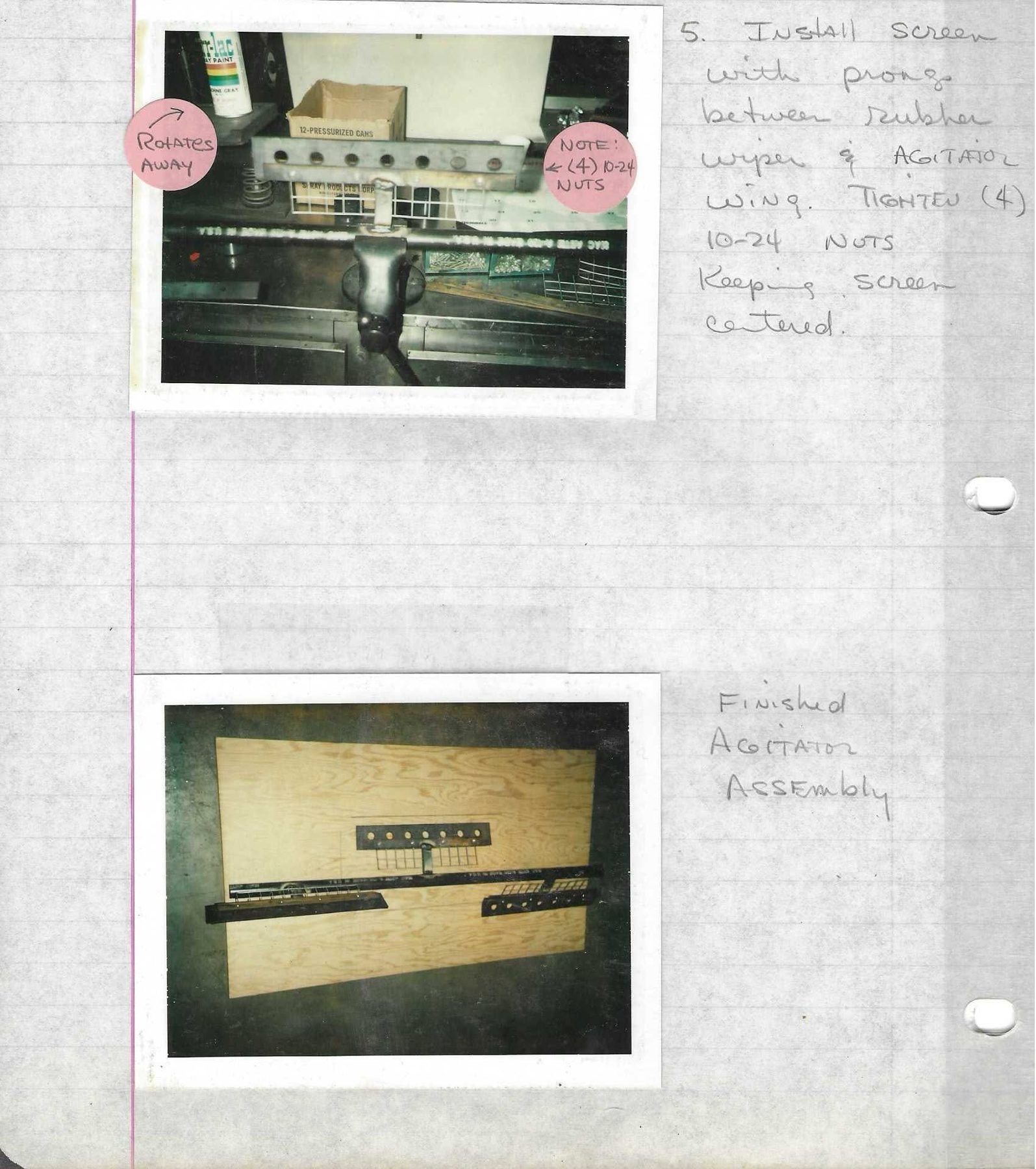
- Wipers. Each blade carries a rubber wiper strip with a row of seven holes, fastened with 10-24 (or 8-32) stove bolts. The bolt heads must "lead" because "AGITATOR turns away from you" (instructions p. 3). The patent specifies tough rubber or neoprene "of the order of 1/4 inch" thick, and a later mailer advertises a "neoprene-bladed agitator."
- Wire screens. A screen 11 × 2 holes, "with prongs", is clamped between each wiper and its blade (instructions pp. 3–4). The documents don't say what these screens are for.
- Shafts. The agitator rides on two 1 in stub shafts, 12 in long on the pulley side (keyed) and 10 in on the other, pinned through a 1/4 in hole about 1 in from the end of the agitator (notes pp. 8, 10).
- Bearings. Fafnir RCJC 1 in four-bolt flange bearings, "NO SUBSTITUTE", with grease fittings facing up. They are bolted to each end plate with 7/16 × 1-1/4 in bolts and copper washers inside the tank, tightened "snug, then 1/2 turn" to seal (notes pp. 7, 9).
- Outlet screen. A 9 × 9 wire screen formed over a template and fitted in the outlet reducer bushing (instructions p. 12). The warranty letter mentions "three different size screens", and the service leaflet advises removing the screen for heavy or fibred coatings.
Drive train
Engine. A horizontal-shaft Briggs & Stratton. The July 1966 price list and the 4 HP mailers specify 4 HP. Bob Ruth's notes (p. 24), a Polaroid decal and the 1977 pump manual cover all say 5 HP. The manual cover records "5 HP Briggs and Stratton Eng S/N 130202 Model # 001501 Horizontal". Speed is set by the governor control (Z). The leaflet says to raise it "approximately 1/2 inch" to start and that "volume output is determined by pump r.p.m."
Clutch. The V-Plex friction clutch mounts on the crankshaft with a 3/16 in key and two set screws. Bob Ruth's notes say to file its outside edge so it doesn't chew the belt and to spray WD-40 on its internal spring (p. 25). At idle it slips, and when the engine is speeded up it grips and the pump starts ("Increase engine speed to engage friction clutch (Q), which starts pump"). The belt should "seat 1/2 way up clutch" (notes p. 26).
Jack shaft and coupling. 3/4 in shaft on pillow blocks shimmed with 3–5 washers, with the thrust collar toward the pump (notes p. 21). The 12 in cast-iron, six-spoke pulley mounts on a 3/4 in bore bushing. Alignment was taken seriously: the pump had to be "SQUARE!" to the engine or it would "cause extreme belt wear" (notes p. 19).
Agitator drive. TRU-RUN (Gates) steel hub 37866 (1 in bore) and rim 37776 make up the big pulley on the agitator shaft; a 1-3/4 in TRU-RUN steel pulley, no. 37322, goes on the jack shaft, and the belt is aligned "until belt runs true" (notes pp. 30–31). The 18 in pulley itself is a white pressed-steel disc on a threaded wheel hub (R), behind a drum-shaped guard (Y) with an expanded-metal face.
Speed arithmetic
Engine speed is not stated in any Jetspray document. Governed Briggs & Stratton engines of this kind typically ran somewhere around 3,000–3,600 rpm, and we use that range as an estimated assumption. The clutch (≈3 in) is also estimated. The 12 in and 18 in pulleys and the 1-3/4 in jack-shaft pulley are documented; we read "1 3/4" as the pulley's outside diameter. Belt slip is ignored.
Treat these figures with care. About 70–90 rpm is a sensible speed for paddles about 13 in in radius: the wiper tips move at roughly 8–10 ft/s, enough to keep cement in suspension without whipping air into it. The engine speed and the clutch size are still estimates. The photographs suggest a clutch pulley of about 4–5 in, which would make every speed above higher, and the engine was often run below full governed speed, because the leaflet says output was set by engine speed. Try other values below.
Try it: drive-speed calculator
Fixed: 12 in pump pulley, 18 in agitator pulley (service leaflet).
The Moyno pump
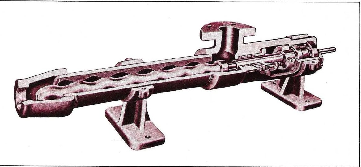
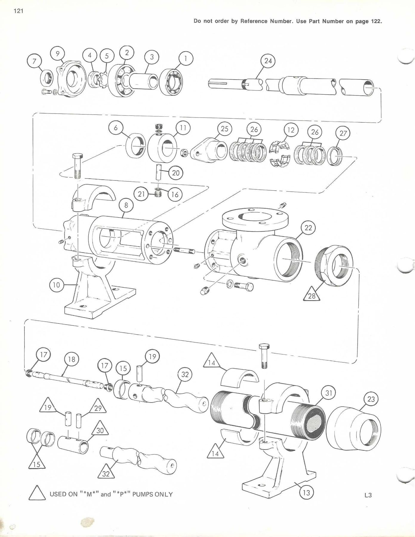
The brochures call it a "helical gear pump", a "helical pump" (1966 price list), a "rotor-stator" pump and, in the later tan brochure, the "ROTOSTATOR." The patent's version is "a well known helical rotor type with resilient housing." The family papers identify it exactly: a Robbins & Myers Moyno progressing-cavity pump. A 1977 Robbins & Myers manual, Operation – Assembly Instructions and Parts List for "L3" Drive End, is annotated by hand: "2L3 Rotor = 13.125 — Standard" and "3L3 Rotor = 18.250 — Heavy Duty."
The manual explains the frame code. The first digit is the number of stages, the letter is the model, and the last digit is the size of the pumping elements. A 2L3 therefore has two stages of size-3 elements, and a 3L3 has three stages, with a longer rotor, 18-1/4 in instead of 13-1/8 in. Each stage is one more sealed cavity between suction and discharge, so a longer, multi-stage element can generally hold more pressure. That explains the "heavy duty" note.
How a single helix pumps
The rotor is a hard steel single helix, like a twisted round bar. The stator is a moulded rubber lining (Buna-N in standard Moyno construction) with a double internal helix of twice the rotor's pitch. Cut across anywhere along its length, the stator's bore is a slot (two semicircles joined by straight sides) and the rotor is a circle. As the shaft turns, the rotor rolls eccentrically inside the slot, sliding from one end of it to the other. Along the length, the rotor and stator touch on continuous seal lines, so they enclose a chain of separate cavities that travel steadily from suction to discharge. The manual adds that as one cavity shrinks, the opposite one grows "at exactly the same rate," which gives an almost pulse-free flow with no valves.
For a roof-coating machine this suited the job well. Gritty, fibred or cement-laden coatings pass through without check valves to foul, the rubber stator tolerates abrasives better than close metal clearances would, and the output is proportional to shaft speed. That is why the leaflet can say volume is set by engine rpm.
How it was installed
Bob Ruth's notes (pp. 16–18, 23) set out the installation. Spacers go under the pump feet and are bolted to the tank brace with four 3/8 × 2 in bolts, left loose at first. The pump bolts to a 1-1/2 in companion flange with 1/2 × 2 in bolts and a rubber gasket. The pump is rotated "to insure a straight flow from tank to pump." The stator clamps ("caps") are tightened evenly because a cap "could break with more tension." Keystone No-Weld anti-seize goes on the pump shaft, and the shaft key is a 1-3/4 × 3/16 in piece filed and bevelled for an easy fit. The shop instructions add that the pump's grease fitting faces up once it is in place, and that the key taped to the new pump's shaft was reused for the engine clutch.
The home-made relief valve
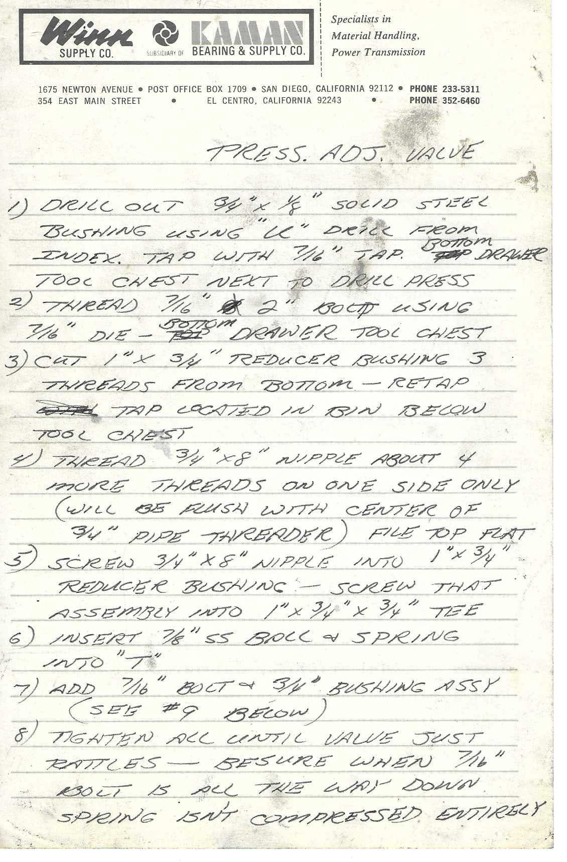
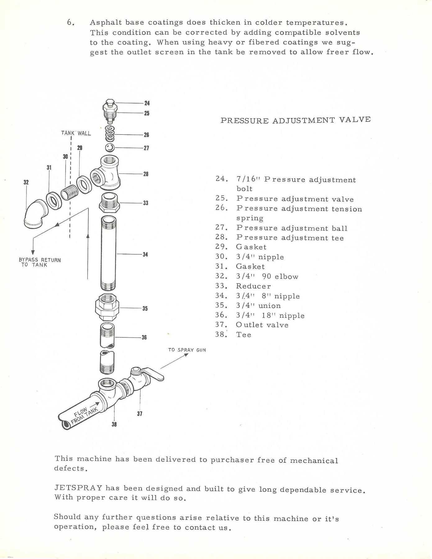
The patent only calls for "spring biased valve means." In the shop that turned into a clever bit of plumbing made from standard pipe fittings, a stainless ball and a bolt. Bob Ruth's notes describe the procedure twice, in pencil (pp. 40–46) and in a neat block-capital version headed "PRESS. ADJ. VALVE" (pp. 3–4 and 50). The printed leaflet gives the finished assembly part numbers 24–38, which are used in the drawing below.
- 247/16-14 × 2 in adjusting bolt, threaded "all the way down to head" with a die; Teflon tape where the old and new threads meet
- 253/4 × 1/8 in forged-steel bushing, drilled with a "U" drill and tapped 7/16-14 right through
- 26Tension spring (size not recorded)
- 277/8 in stainless-steel ball
- 281 × 3/4 × 3/4 in tee: the valve body
- 29, 31Gaskets, 1 in ID × 1-1/2 in OD × 3/16 in, either side of the tank wall
- 303/4 in close nipple through a 1-1/8 in Greenlee-punched hole
- 323/4 in 90° elbow inside the tank, pointing down
- 331 × 3/4 in reducer bushing, "cut ≈3 threads off (where inside threads stop)" and re-tapped 3/4-14
- 343/4 × 8 in nipple, extra-threaded on one end, top "file[d] flat" as the seat
Below 34: the 3/4 in union (35), the 3/4 × 18 in riser (36) and the tee at the pump (38), where the outlet ball valve (37) is fitted.
How it was made
Bob Ruth's block-capital version, steps 1–9 (notes pp. 3–4 and 50; detail from pp. 40–46):
- Drill out a 3/4 × 1/8 in solid steel bushing with a "U" drill and tap it 7/16-14.
- Thread a 7/16 × 2 in bolt the full length with a 7/16 die.
- Cut three threads off the bottom of a 1 × 3/4 in reducer bushing and re-tap it.
- Thread a 3/4 × 8 in nipple about four more threads on one end only, and file that end flat.
- Screw the nipple into the reducer bushing until its threads come through, then screw that assembly into the 1 × 3/4 × 3/4 in tee.
- Drop in the 7/8 in stainless ball and the spring.
- Add the bolt and bushing assembly (step 9).
- "Tighten all until valve just rattles." Make sure that with the bolt all the way down, the spring is not fully compressed.
- The bushing assembly: screw the bolt in until its head is 3/16 in above the bushing, checked with a horseshoe gauge. Snug a nut onto the bottom, drill through nut and bolt with a #29 drill, and pin it with a piece of nail left 1/16 in proud each side and peened in a vise ("one nail will do ≈3 pressure adjustment valves").
How it works, and what the numbers imply
Pump pressure acts up through the bore of the 8 in nipple on the underside of the ball. When that force beats the spring, the ball lifts and coating squeezes around it and out of the tee's side branch, straight back into the tank. Screwing the bolt down compresses the spring and raises the relief pressure. The operator sets it while watching the gauge (O).
Our reading of the design (interpretation, not stated in the notes):
- The 1 in run of the tee is on the seat side for a reason. A 1 in fitting's bore (about 1.05 in) leaves an annulus around the 7/8 in ball for the returning coating to pass through. The nipple, threaded through the shortened bushing, puts the seat right inside that larger bore.
- The pinned nut and the 3/16 in head gap look like a pair of stops. The bolt can travel only between the head bottoming on the bushing (maximum spring load) and the nut hitting the bushing's underside (minimum). With 14 threads per inch, 3/16 in is about 2-5/8 turns. The pin also means the bolt can't be unscrewed out of a pressurised valve.
- Steps 8 and p. 46 ("loosen adjustment bolt and check for end play … a small rattle") then set the range. At the loosest position the ball must have a little free play, so the valve can be fully released to flush debris (leaflet, step 4b). At the tightest, the spring must not go solid.
If our reading of the 3/16 in stops is right, reaching 250 psi within that travel would take a stiff spring, on the order of 700 lb/in or more. The spring's rate is not recorded anywhere, so the pressure per turn can't be calculated.
Hydraulics sanity check
The power that ends up in the fluid is flow times pressure. In US units, hydraulic horsepower = gpm × psi ÷ 1714. Applying that to the advertised figures:
| Claim | Source | Hydraulic hp | Shaft hp (est.) |
|---|---|---|---|
| 6 gpm @ 200 psi | Early magenta brochure | 0.70 | 1.0–1.4 |
| 7 gpm @ 250 psi | 1967 mailer, orange & green mailers | 1.02 | 1.5–2.0 |
| 7 gpm @ 1,000 psi | Tan brochure ("up to") | 4.08 | 5.8–8.2 |
The 6–7 gpm, 200–250 psi ratings call for one or two horsepower at the pump shaft. With agitator and belt losses added, they sit comfortably within a 4–5 HP engine. The tan brochure's "up to 1,000 lbs. with heavier coatings" cannot happen at the same time as its "up to 7 gpm". That combination needs more power than the engine has, so 1,000 psi could only apply at a much lower flow. The documents don't say whether the 2L3 elements were rated that high. We suspect the figure refers to a short-term pressure capability rather than a working point, but that is a guess.
Other useful numbers
Hose areas use nominal bore. The move from 50 ft of 1/2 in hose (1966 price list) to 150 ft of 3/4 in (later brochure) roughly halved the flow velocity. That matters with heavy, fibred coatings, because friction loss rises steeply with velocity. Both effects are general fluid mechanics; no Jetspray document discusses them.
Operating & cleaning
From the printed Service and Operating Instructions leaflet (letters refer to its photographs), with the patent's description of the same cycle.
Leaflet warning: "do not run pump when dry. Prime pump and hose before putting coating into machine."
To start
- Check oil, lubrication and gas in the engine.
- Release the tension on the pressure adjustment valve (S).
- Attach the hose and spray gun to the outlet valve (X). Put the gun's nozzle back into the tank and open X so everything circulates freely. Make sure the tank has the correct solvent.
- Raise the governor adjustment (Z) about 1/2 in, pull out the choke, and start.
To operate
- Speed up the engine to engage the friction clutch (Q); this starts the pump. Set engine speed for the output wanted.
- Set the pressure adjustment valve (S) while watching the gauge (O).
Mixing and spraying
- Pour in a compatible solvent first, then the coating. The machine mixes it "to uniform texture" while it recirculates. When it is mixed, shut X, set S to the working pressure, and spray.
- Coating can be added without stopping the machine.
- The patent describes the cement version of the same cycle. With the main cock closed, pour in water, set a bag of Portland cement on the loading screen, cut it open with a shovel and let it fall through into the liquid. The patent also names "Alumination 301" (Republic Powdered Metals Co.) as a suitable coating.
- Spray pattern is set by the nozzle. Volume is set by the by-pass spring and the engine speed (patent).
When it clogs
- Gun stops spraying: debris in the nozzle. Close X, remove the nozzle and clean it.
- Debris in the relief-valve seat: release all tension on S and close X. The free return flow through S will wash the obstruction out.
- Asphalt-base coatings thicken in the cold; thin them with compatible solvent. For heavy or fibred coatings, remove the outlet screen in the tank.
Cleaning
- Clean thoroughly after every day's use. Drain the tank, clean with solvent, then run water through the tank, pump and hose to flush out all solvent (leaflet).
- The patent adds two details. Keep the engine running while draining so the aggregate doesn't settle. During the water flush, close the gun valve from time to time so the cleaning liquid also flushes the by-pass line and pressure valve.
Specifications by document
The sales literature changed over the years, and the documents genuinely disagree. Only two pieces carry a date: the July 1966 price list and the "New 1967 Model" mailer. The others are listed roughly in the order their content suggests. The early pieces give the 2223 El Cajon Blvd. address and the later tan brochure gives 6308 Riverdale St. Highlighted cells are where a figure changes.
| Item | Price list, July 1966 | Magenta brochure (early) | "New 1967 Model" mailer | Orange mailer | Green & yellow mailer | Tan brochure (later) |
|---|---|---|---|---|---|---|
| Engine | 4 HP Briggs & Stratton, friction-clutch PTO | "small gasoline engine", friction-clutch PTO | 4 HP, V-Plex clutch | 4 HP, V-Plex clutch | 4 HP, V-Plex clutch | 5 HP, V-Plex clutch |
| Pump | "helical pump" | "helical gear pump" | — | rotor-stator | rotor-stator | "ROTOSTATOR" |
| Tank | — | 130 gal | 130 gal | 125 gal | 125 gal | 125 gal |
| Weight | — | 400 lb | "Only 400 lbs." | 430 lb | 430 lb | 430 lb |
| H × L × W | — | 44 × 54 × 28 in | — | 44 × 54 × 29 in | 44 × 54 × 29 in | 44 × 54 × 29 in |
| Output | — | up to 6 gpm (360 gal/hr) | up to 7 gpm | up to 7 gpm | up to 7 gpm | up to 7 gpm |
| Pressure | (hose rated 200 lb) | up to 200 psi | adjustable, up to 250 psi | up to 250 lb | up to 250 lb | "up to 350 lbs. with water and up to 1,000 lbs. with heavier coatings" |
| Hose | 50 ft, 1/2 in, 200 lb, with adapters | — | — | — | — | 150 ft, 3/4 in heavy-duty Buna-N-lined; 4 assorted nozzles |
| Agitator | "tank unit, agitator" | — | tank-length agitator; built-in outlet screen | — | full-length neoprene-bladed; Oilite bearings, packed; self-cleaning outlet screen | — |
| Fuel | — | gas & oil "less than 50¢ per roof" (testimonial) | less than 1 qt per tank | — | less than 1 qt per tank | — |
| Guarantee | — | 10-day free trial | 1 year + 10-day money back | 1 year + 10-day refund | 1 year + 10-day money back | — |
| Price | $1,260.00 complete, F.O.B. San Diego | — | — | — | — | — |
Other sources: Bob Ruth's assembly notes (p. 24) and a 1977 Robbins & Myers manual annotation both say 5 HP Briggs & Stratton. An undated letter signed by David Eliason, Sales Manager, extends the guarantee "to 90 days" and adds "three different size screens and nozzles". That conflicts with the one-year guarantee in the mailers, so it is probably an earlier letter, but it is undated. The patent prototype held 60–75 gal.
How we reconstructed it
No Jetspray machine is known to survive, and no factory drawings have been found. The 3D model and the drawings on this page were rebuilt from the documents, and every dimension is kept in one file (cad/spec.py, published as /data/spec.json) with its status and source:
- documented stated in a period document (cited);
- derived calculated from documented values (method cited);
- estimated judged from photographs and proportions; open to correction.
If you have a Jetspray part, photograph or measurement that pins down an estimated value, the family would love to hear from you.
| Dimension | Value | Status | Source / method |
|---|---|---|---|
| Loading dimensions… | |||
Open questions. (1) The size of the V-Plex clutch pulley and the engine's working speed, and therefore every speed on this page. (2) Whether the "14 in centre" means 14 in below the rim. (3) The blade sweep and the loading screen. With the shaft 14 in below the rim, the wiper tips pass within about an inch of the rim, so the loading screen must have sat in that last inch, right under the lid. The reconstruction places it 0.6 in down; the patent drawing (FIG. 2) shows it just as close. (4) The relief-valve spring, and the engine's actual working speed.
Patent legacy
Prior art cited by the examiner
- 455,463 Pratt, June 1891 (239-126). Insecticide distributer.
- 2,580,551 Kacena, Jan. 1952 (259-178). Scraper blade for plaster mixers.
- 2,596,074 Hawes, May 1952 (239-127).
- 2,618,576 Brown et al., Nov. 1952 (259-161).
- 2,880,976 True, Apr. 1959 (239-124). Mobile concrete mixer and sprayer.
- 2,976,025 Pro, Mar. 1961 (259-178). Mixer/conveyor (Air Placement Equipment).
Numbers, dates and classes are as printed on the patent. Subjects are from Google Patents where known.
Later patents that cite it
- US 3,716,066 (1973) 3M: aircraft cleaning
- US 3,759,492 (1973) concrete mixing system
- US 3,881,654 (1975) Gates Rubber: battery paste pumping
- US 4,075,713 (1978) feed mixer
- US 4,117,547 (1978) Mathis Fertigputz: mortar
- US 4,311,274 (1982) mobile protective-coating sprayer
- US 4,599,004 (1986) mixing tank for spray chemicals
- US 4,600,150 (1986) screw-conveyor spraying system
- US 4,695,167 (1987) Shinagawa Refractories: slurry
- US 4,705,217 (1987) material mixing and spraying
- US 5,060,865 (1991) ICI: fluid flow restrictor
- US 5,164,165 (1992) drinking fountain
- US 5,284,296 (1994) Magneco/Metrel: ceramic slurries
- US 5,361,711 (1994) seeding and mulching
- US 6,050,721 (2000) plasticizable compounds
- US 2002/0093876 & US 6,565,252 (2002/2003) Renegade Tool: interior finishing
- US 6,886,974 (2005) Northrop Grumman: fluid agitation
Citation list from Google Patents. Being cited means a later examiner or applicant considered the Jetspray patent relevant prior art. It does not mean the later invention used Alex's design.
The citing patents cover a wide range: cement and mortar, refractory and ceramic slurries, battery paste, hydro-seeding, agricultural chemicals and aircraft cleaning. The common thread is the problem the Jetspray solved, which is keeping a heavy, settling mixture stirred and pumping it out of the bottom of a tank without clogging.
Sources
- U.S. Patent 3,203,631, A. O. Jutila, "Abrasive Type Roof Coating Apparatus," filed May 18, 1964, issued Aug. 31, 1965. PDF.
- Airless Jetspray Service and Operating Instructions, Jetspray Products, Inc., 6308 Riverdale St. (4 pp.), with photo callouts C–Z and the pressure-adjustment-valve drawing, parts 24–38.
- Bob Ruth's shop and assembly notes, 50 handwritten pages, mostly on Winn Supply Co. (Kaman Bearing & Supply) notepads. Page numbers on this page refer to the scan order.
- Shop instructions with Polaroids, 12 pages, and shop photographs, 14 pages, in the family archive.
- Sales literature: early magenta brochure; "New 1967 Model" mailer; orange self-mailer; green-and-yellow mailer; tan brochure; Equipment Price List, July 1966; undated guarantee letter signed by David Eliason, Sales Manager.
- Robbins & Myers, "Operation – Assembly Instructions and Parts List for 'L3' Drive End," Section 25, Aug. 1, 1977, with handwritten annotations.
- Reconstruction data: /data/spec.json; 3D model.