Build a 1:6 Jetspray
A mixed-media kit for the best model of the machine we can make: printed castings and fittings, a soldered brass-angle frame, a hand-rolled sheet tank, real mesh, rubber belts and a silicone hose. Every part comes straight from the same parametric model that drives the 3D viewer.
The stock lands on the sizes
At one-sixth size the machine is 9.4 × 5.1 × 7.5 in (238 × 131 × 190 mm) over the pulley guard and plumbing — big enough to show the wiper blades, the relief valve and the belt drive, small enough for a shelf.
The real reason is the plumbing. Divide standard pipe and shaft sizes by six and they land on hobby brass you can buy off the rack, so the pipework is real tube, not printed approximations.
1:6 is also the scale of 12-inch action figures. A 1:6 roofer can stand beside the machine holding the spray wand, which tells the story of a one-man machine better than any caption.
- 1 in pipe agitator hub, discharge nipple · 1.315 in OD7/32 in K&S tube 5.56 mm · exact
- 3/4 in shaft jack shaft · documented1/8 in rod 3.18 mm · exact
- 1-1/2 in pipe suction drop · 1.900 in OD5/16 in tube 7.94 mm · within 1%
- 3/4 in pipe riser, seat nipple · 1.050 in OD4.5 mm tube Albion; 3/16 in K&S also works
- 1 in shafts agitator stubs · documented5/32 in rod in 3/16 in sleeves inside the 7/32 hub
- 1-1/4 in angle frame · estimate5 mm or 3/16 in angle 5.3 mm would be exact
Every part, in 3D
The build steps below link into the viewer with the machine pulled apart, so you can turn each part over before you make it.
Tools & materials
Printing
- MSLA resin printer (4K or better) for the castings, fittings and pulleys
- FDM is fine for the spacers, stator and pillow block
- Grey resin, IPA wash, UV cure
- Pin vise and drills: 0.8, 1.0, 1.6, 3.2, 4.0, 4.6, 5.75 and 8.1 mm
Metalwork
- Jeweller's saw, small snips, needle files, deburring tool
- Small sheet-metal folder (or two steel bars and a vise)
- A round former just under 112 mm for the tank bottom; an 85 mm one for the guard
- Tube cutter, bending springs, fine sand to pack the suction bend
- Soldering iron or resistance unit, low-melt solder, flux; CA and epoxy
- Flat build board, engineer's square, digital calipers
Materials
- 0.3–0.4 mm brass or tin-plate sheet, about 320 × 200 mm plus offcuts
- Brass angle, strip, tube and rod — see the cut list
- Fine brass or aluminium mesh
- 1 mm black rubber sheet, 1.5 mm O-ring cord, 8 mm and 3 mm ID silicone tube
- 4 mm steel ball, a pen spring
- Spray mount (to stick paper templates to the sheet), primer, paints
The kit files
Complete kit
All 28 STLs in millimetres at 1:6, the print variants, every template (SVG and PDF), the cut list and bill of materials as CSV and Markdown, the printing guide and a README.
Download kitSheet-metal templates
Six US-Letter sheets (they fit A4 width too) plus a one-piece tank wrap for A3 / Tabloid. Print at 100%, then check the 25 mm and 1 in squares.
Templates PDFFull-size CAD
The whole machine as a STEP assembly in inches, for anyone who wants to re-scale, re-cut or machine parts.
Download STEPSheets in the template set: T1 & T2 tank wrap (tape together at the bottom centre line) · T3 two U-shaped end plates with bearing bore, bolt holes and the return hole · T4 lid with fold lines and corner reliefs · T5 pulley-guard band and the four leg braces · T6 loading screen, guard face and outlet screen.
Follow the shop order
The steps follow Bob Ruth's shop notes, the hand-written, Polaroid-illustrated procedure used to finish machines in the Jetspray shop. Page numbers point to the transcriptions in the archive. Part tags open the 3D viewer with that part selected.
In the shop the tank and stand arrived already welded, so Bob's notes begin with painting. At 1:6 you make the frame and tank first, then follow his order from the agitator onwards.
-
Frame and base slats
Lay the long rails on a flat board, notch their outer legs back one leg-width at each end, and stand the posts between them. End rails butt between the posts. Square everything, pin it, solder. Add the four base slats across the bottom rails at the positions in the cut list.
-
Tank shell and end plates
Tape templates T1 and T2 together, spray-mount to the sheet and cut. Roll the top edges over 1.2 mm wire for the rolled lip, then roll the half-round bottom. Cut the two end plates (T3) and fit them inside the wrap. Drill the bearing holes on the shaft centre — Bob's notes mark it 14 in below the rim, with four 7/16 in holes and a centre hole opened with a 1 in Greenlee punch — and punch the bottom-centre outlet.
Bob Ruth's notes: instructions p1–2; notes p5.
-
Agitator assembly
Glue the rubber wipers to the three printed blade units (Bob bolted them with 10-24 stove bolts, heads leading, because the agitator "rotates away from you"). Thread the units onto the 7/32 in brass hub: the centre blade one way, the two outer blades the other.
Bob Ruth's notes: instructions p3–4; notes p6.
-
Stub shafts and bearings
Cut the 12 in (drive, pulley side) and 10 in (idle) stubs from 5/32 in rod and slide on the printed flange bearings — Fafnir RCJC 1 in in the shop, "NO SUBSTITUTE". Grease fittings face up.
Bob Ruth's notes: instructions p5–6; notes p7–8.
-
Install the agitator
Bolt one bearing to the tank end (in the shop: bolt heads and copper washers inside, snug then half a turn). Set the agitator in, centre blade down over the outlet, fit the other shaft and bearing. Pitch the outer blades "left down, right up", then cross-drill and pin hub to stub about 1 in (4.2 mm at 1:6) from each end of the agitator.
Bob Ruth's notes: instructions p7–8; notes p9–10.
-
Leg braces
Rivet the four straps (template T5, two marked L, two R) through the centre of the rolled lip, heads inside, and fix their lower ends to the base. 1 mm brass wire peened over makes a convincing 1/4 in rivet.
Bob Ruth's notes: instructions p2, p9; notes p5, p11.
-
Lid and screens
Fold the lid (T4): long skirts first, then the ends. Fit hinges along the back and latches at the front. Solder the loading screen (T6) to its side bars and drop it in just under the rim; lay the outlet screen over the outlet.
Bob Ruth's notes: instructions p10, p12. Patent items 19, 27, 28.
-
Pump and suction
Set the spacers on the slats and the pump on the spacers, square to where the engine will go. Add the companion flange, then the suction drop from the printed bushing in the tank bottom down to the pump inlet, joined by a sleeve of silicone tube for the no-hub coupling.
Bob Ruth's notes: instructions p11; notes p15–19.
-
Jack shaft, pulley and coupling
Fit the pillow block at the frame end — Bob shimmed it with 3 to 5 washers, thrust collar toward the pump. Slide the 12 in pulley onto the 1/8 in jack shaft and join it to the pump with the jaw coupling.
Bob Ruth's notes: notes p20–23, p28–29.
-
Engine and clutch
Put the V-Plex clutch on the crankshaft, set the engine on the base and slide it until the belt is snug and sits about half way up the clutch, then fix it down. Fit the pump drive belt.
Bob Ruth's notes: notes p24–27.
-
Agitator drive and pulley guard
Wheel hub and 18 in pulley on the drive stub, the small pulley on the end of the jack shaft, then the agitator belt. Roll the guard band (T5), fit the mesh face (T6) and fix the guard over the pulley — Bob's notes rivet it to two L-brackets at the top and a brace at the bottom.
Bob Ruth's notes: notes p30–35.
-
Discharge and relief valve
Reducer coupling with the gauge on the pump outlet, the 1 × 4-1/2 in nipple, the tee, close nipple, ball valve and hose adapter. Up the tee goes the 18 in riser and union. The relief valve is built from fittings, as in the shop: the 8 in seat nipple filed flat on top, a 7/8 in ball (4 mm at 1:6) and spring, the adjusting bolt — set "until valve just rattles" — and the return through the 1-1/8 in hole in the end plate.
Bob Ruth's notes: notes p3–4, p36–48, p50.
-
Paint, then join at the union
Exactly as Bob's notes say: paint the lower and upper plumbing assemblies separately, then connect them at the union and tighten. On the model, leave the union joint unglued until the paint is done.
Bob Ruth's notes: notes p46, p49.
-
Hose and gun
Push the silicone hose onto the hose adapter and coil it. Assemble the printed gun grip and nozzle on a 2 mm brass wand.
Make it move
The working parts turn like the real machine's: engine clutch → belt → 12 in pump pulley and jack shaft → pump coupling and the small pulley → belt → 18 in pulley → agitator paddles. Both belts are open (not crossed), so every pulley turns the same way.
Shafts in brass bushings
The 1/8 in jack shaft runs in 5/32 in brass-tube bushings in the pillow block and at both ends of the pump bearing housing (pump_bearing_print.stl). The 5/32 in agitator stubs run in 3/16 in tube in both flange bearings. Glue the pulleys and coupling to their shafts.
A motor inside the engine
An N20 gearmotor (6 V, 200–300 rpm, 3 mm D shaft) slides into the pocket in engine_print.stl from the starter end. crank_print.stl pushes onto its shaft, and starter_cap_print.stl closes the pocket. The wires drop through a hole under the blower housing to 2 × AA or a 5 V USB lead.
Speeds
At 300 rpm the clutch turns at 300 rpm, the pump pulley and jack shaft at about 68 rpm, and the agitator at about 6 rpm. That is roughly a tenth of the real machine's speeds, which reads well at this size. No motor? Flick the 12 in pulley: the agitator turns once for about every 11 turns of it.
Belts, wipers and lid
Cut the O-ring cord 8% short of the pitch length (cut list) so it grips. The wipers should just touch the tank bottom, about 0.6 mm at this scale; trim them if the agitator drags. For a lid that opens, make the hinge knuckles from 1/32 in brass tube on shim leaves with a 0.5 mm wire pin.
Metal & stock
Lengths at 1:6, generated from the model. The basis tag passes through where the driving dimension came from: documented in a period document, derived from documented values, or estimate.
Frame
| Item | Qty | Cut length | Section | Suggested stock | Basis | Notes |
|---|---|---|---|---|---|---|
| Long rails, top & bottom frame | 4 | 199.0 mm 7.83 in | 5.3 x 5.3 x 0.8 mm angle | 3/16 in or 5 mm brass angle (5.3 mm leg is exact 1:6 of the 1-1/4 in estimate) | derived | Full frame length. Notch the outer (vertical) leg back 5.3 mm at each end so the horizontal leg laps over the post end. |
| Corner posts frame | 4 | 184.0 mm 7.25 in | 5.3 x 5.3 x 0.8 mm angle | 3/16 in or 5 mm brass angle (5.3 mm leg is exact 1:6 of the 1-1/4 in estimate) | documented | Square-cut. Frame height less the two rail thicknesses; rails lap on top and bottom. |
| End rails, top & bottom frame | 4 | 112.2 mm 4.42 in | 5.3 x 5.3 x 0.8 mm angle | 3/16 in or 5 mm brass angle (5.3 mm leg is exact 1:6 of the 1-1/4 in estimate) | estimate | Square-cut butt between the posts' end-face legs (exactly as modelled). |
| Base slats slats | 4 | 121.2 mm 4.77 in | 8.5 x 1.99 mm flat | 8 x 1 mm or 5/16 x 1/32 in brass strip | estimate | Across the bottom rails. Centres at 40, 119, 152, 193 mm from the -X (plumbing) end. |
Tank
| Item | Qty | Cut length | Section | Suggested stock | Basis | Notes |
|---|---|---|---|---|---|---|
| Leg braces (straps) straps | 4 | 182.9 mm 7.20 in | 5.1 x 1.65 mm flat | 3/16 x 1/32 in (4.8 x 0.8 mm) brass strip | estimate | Template T5 gives the hole positions. 2 marked L, 2 marked R. |
| Lid handle lid | 1 | 32.2 mm 1.27 in | 2.1 x 0.85 mm | 2 x 0.8 mm brass strip (or 1 mm wire) | estimate | Bend to a U: 25.4 mm grip, 3.4 mm legs. |
| Loading-screen side bars screen | 2 | 185.6 mm 7.31 in | 2.5 mm square | 3/32 in (2.4 mm) square brass bar | estimate | Solder the mesh (T6) between them. |
| Tank lip wire tank | 2 | 186.3 mm 7.33 in | Ø1.2 mm | 1.2 mm (3/64 in) brass wire | estimate | Rolled into the top edge of each side (template T1/T2). |
Agitator
| Item | Qty | Cut length | Section | Suggested stock | Basis | Notes |
|---|---|---|---|---|---|---|
| Agitator hub (1 in pipe) agitator | 1 | 179.9 mm 7.08 in | Ø5.57 mm tube | 7/32 in K&S brass tube (5.56 mm = exact 1:6 of 1 in pipe) | derived | The print-variant blades thread onto this tube. Model length = tank length - 1.5 in. |
| Hub sleeves agitator | 2 | 20.0 mm 0.79 in | Ø4.76 mm tube | 3/16 in K&S brass tube (telescopes into 7/32) | estimate | Kit detail, not in the model: slide into each end of the hub so the 5/32 in stub shafts fit snugly. |
| Idle stub shaft (1 x 10 in) stub_idle | 1 | 42.3 mm 1.67 in | Ø4.23 mm rod | 5/32 in steel or brass rod (3.97 mm; 4 mm also fine) | documented | -X end. Pinned 1 in from the end of the agitator. |
| Drive stub shaft (1 x 12 in) stub_drive | 1 | 50.8 mm 2.00 in | Ø4.23 mm rod | 5/32 in steel or brass rod | documented | +X (pulley) end; carries the 18 in pulley and wheel hub. |
| Agitator pins (1/4 in) agitator | 2 | 6.8 mm 0.27 in | Ø1.0 mm wire | 1 mm brass wire | documented | Through hub and stub, 4.2 mm from each end of the agitator (notes p10). |
| Bushings, agitator stubs bearing_drive | 2 | 7.6 mm 0.30 in | 3/16 in tube | K&S 3/16 in brass tube (ID 4.05 mm) | model | Press into each flange bearing (drill 4.8 mm). The 5/32 in stub shafts turn inside. |
| Centre-blade wiper wipers | 1 | 50.8 mm 2.00 in | 11.1 x 1.06 mm | 1 mm black craft rubber / neoprene sheet | estimate | 50.8 x 11.1 mm strip; 1/4 in neoprene (patent). |
| Outer-blade wipers wipers | 2 | 46.6 mm 1.83 in | 11.1 x 1.06 mm | 1 mm black craft rubber / neoprene sheet | estimate | 46.6 x 11.1 mm strips. |
Drive
| Item | Qty | Cut length | Section | Suggested stock | Basis | Notes |
|---|---|---|---|---|---|---|
| Jack shaft (3/4 in) jack_shaft | 1 | 96.1 mm 3.78 in | Ø3.17 mm rod | 1/8 in steel rod (3.18 mm = exact 1:6) | documented | Runs from inside the pump bearing housing, through the coupling, pillow block and 12 in pulley to the small agitator pulley - longer than the visible shaft so it has two bearings. |
| Bushings, 1/8 in shafts pillow_block | 3 | 7.6 mm 0.30 in | 5/32 in tube | K&S 5/32 in brass tube (ID 3.26 mm) | model | Press into the pillow block and both ends of the pump bearing housing (drill 4.0 mm). The 1/8 in jack shaft turns inside. |
| Gearmotor (optional) engine | 1 | 0.0 mm 0.00 in | N20, 3 mm D shaft | N20 gearmotor, 6 V, 200-300 rpm, 3 mm D shaft | model | Hides inside engine_print.stl and drives the clutch pulley directly. 2 x AA or a USB 5 V lead under the base. |
Plumbing
| Item | Qty | Cut length | Section | Suggested stock | Basis | Notes |
|---|---|---|---|---|---|---|
| Suction drop (1-1/2 in) suction_pipe | 1 | 25.9 mm 1.02 in | Ø8.04 mm tube | 5/16 in K&S brass tube (7.94 mm) or 8 mm Albion | derived | 4.4 mm straight down from the bushing, then bend 58° and run 20.0 mm back to the pump inlet. Service leaflet calls it a 45° street ell; the model geometry needs 58°. Pack with fine sand or use a bending spring. |
| No-hub coupling nohub | 1 | 10.0 mm 0.39 in | 8 mm ID silicone tube | 8 mm ID x 10-11 mm OD black silicone tube | estimate | Slides over the suction drop; add two 0.3 mm shim clamp bands. |
| Discharge nipple (1 x 4-1/2 in) discharge | 1 | 19.7 mm 0.78 in | Ø5.57 mm tube | 7/32 in K&S brass tube (exact 1:6 of 1 in pipe) | documented | Visible 16.7 mm between the printed reducer coupling and tee (+1.5 mm over each printed spigot). 4-1/2 in nipple documented in notes p37. |
| Close nipple (3/4 in) discharge | 1 | 5.8 mm 0.23 in | Ø4.45 mm tube | 4.5 mm Albion or 3/16 in K&S brass tube | documented | Tee -> ball valve (notes p38). |
| Return riser (3/4 x 18 in) riser | 1 | 79.2 mm 3.12 in | Ø4.45 mm tube | 4.5 mm Albion or 3/16 in K&S brass tube | documented | Visible 76.2 mm, tee to union. Galvanised finish. |
| Valve seat nipple (3/4 x 8 in) seat_nipple | 1 | 38.1 mm 1.50 in | Ø4.45 mm tube | 4.5 mm Albion or 3/16 in K&S brass tube | documented | Visible 35.1 mm, union to relief-valve tee; file the top end flat - it is the valve seat. |
| Return nipple into tank end relief_tee | 1 | 11.9 mm 0.47 in | Ø5.1 mm | Included in relief_tee.stl - or 4.5 mm tube if you split it | estimate | Through the 1-1/8 in hole in the -X end plate. Bob Ruth's notes p48 add a 3/4 in 90° elbow inside the tank (not modelled). |
| Hose (3/4 in, 150 ft) | 1 | 1000.0 mm 39.37 in | 3 mm ID silicone tube | 3 mm ID x 5 mm OD silicone tube, dark red or black | documented | Full scale is 7.62 m at 1:6 - a 1 m coil on the display base reads well. |
| Spray-gun wand gun | 1 | 149.8 mm 5.90 in | Ø2.12 mm rod | 2 mm or 3/32 in brass rod / tube | estimate | Fits the two sockets of the gun_body/gun_nozzle print variants (4 mm deep). |
Belts
| Item | Qty | Cut length | Section | Suggested stock | Basis | Notes |
|---|---|---|---|---|---|---|
| Pump drive belt belt_pump | 1 | 186.2 mm 7.33 in | Ø1.5 mm cord | 1.5 mm black Buna O-ring cord (1 mm also works) | estimate | Cut 8% shorter than the 202 mm pitch length so it grips; butt-join with CA. The clutch size is an estimate. |
| Agitator belt belt_agit | 1 | 300.1 mm 11.81 in | Ø1.5 mm cord | 1.5 mm black Buna O-ring cord | derived | Cut 8% shorter than the 326 mm pitch length so it grips; butt-join with CA. Jack-shaft pulley -> 18 in pulley (1-3/4 in TRU-RUN pulley, Bob Ruth's notes p31). |
Relief valve
| Item | Qty | Cut length | Section | Suggested stock | Basis | Notes |
|---|---|---|---|---|---|---|
| Relief spring relief_spring | 1 | 5.0 mm 0.20 in | Ø3.3 mm coil | Ballpoint-pen spring, or 0.25 mm wire on a 2.3 mm mandrel | estimate | About 10 turns. |
Stock to buy
| Stock | Total length | Buy |
|---|---|---|
| 3/16 in or 5 mm brass angle | 1981 mm | 8 x 305 mm (12 in) length |
| 8 x 1 mm or 5/16 x 1/32 in brass strip | 485 mm | 2 x 305 mm (12 in) length |
| 3/16 x 1/32 in | 732 mm | 4 x 305 mm (12 in) length |
| 2 x 0.8 mm brass strip | 32 mm | 1 x 305 mm (12 in) length |
| 3/32 in | 371 mm | 2 x 305 mm (12 in) length |
| 1.2 mm | 373 mm | 2 x 305 mm (12 in) length |
| 7/32 in K&S brass tube | 200 mm | 1 x 305 mm (12 in) length |
| 3/16 in K&S brass tube | 40 mm | 1 x 305 mm (12 in) length |
| 5/32 in steel or brass rod | 93 mm | 1 x 305 mm (12 in) length |
| 1 mm brass wire | 14 mm | 1 x 305 mm (12 in) length |
| 1/8 in steel rod | 96 mm | 1 x 305 mm (12 in) length |
| K&S 5/32 in brass tube | 23 mm | 1 x 305 mm (12 in) length |
| K&S 3/16 in brass tube | 15 mm | 1 x 305 mm (12 in) length |
| N20 gearmotor, 6 V, 200-300 rpm, 3 mm D shaft | 0 mm | 1 x 305 mm (12 in) length |
| 5/16 in K&S brass tube | 26 mm | 1 x 305 mm (12 in) length |
| 4.5 mm Albion or 3/16 in K&S brass tube | 123 mm | 1 x 305 mm (12 in) length |
| 2 mm or 3/32 in brass rod / tube | 150 mm | 1 x 305 mm (12 in) length |
Bend allowances for thin sheet
90° bends with an inside radius equal to the sheet thickness (K-factor 0.42). For a part dimensioned outside, subtract one bend deduction per bend. The wired edge is the tank's rolled lip, wrapped about 270° round the wire. The templates are drawn for 0.35 mm sheet.
| Sheet | Bend allowance 90° | Bend deduction 90° | Wired edge, 1.0 mm wire | Wired edge, 1.2 mm wire |
|---|---|---|---|---|
| 0.30 mm | 0.67 | 0.53 | 3.06 | 3.53 |
| 0.35 mm | 0.78 | 0.62 | 3.18 | 3.65 |
| 0.40 mm | 0.89 | 0.71 | 3.30 | 3.77 |
Every part, and how to make it
All 50 parts in the model, plus the hose. Names open the part in the 3D viewer.
| Part | Group | Make it as | Qty | Material / files |
|---|---|---|---|---|
| Angle-iron frame frame | Frame | Brass angle, soldered | 12 | 5.3 mm brass angle (cut list) |
| Base slats slats | Frame | Brass strip | 4 | 8 x 1 mm brass strip |
| Mixing tank tank | Tank | Bent sheet + 2 end plates | 1 | 0.35 mm brass / tin-plate, templates T1-T3 |
| Tank leg braces straps | Tank | Brass strip | 4 | 4.8 x 0.8 mm brass strip, template T5 |
| Nameplate nameplate | Tank | decal | 1 | Decal 36 x 13 mm. The artwork is drawn in the 3D viewer; a printable decal sheet is not in the kit yet |
| Loading screen screen | Tank | Mesh on strip frame | 1 | Fine brass mesh, template T6 |
| Hinged lid lid | Tank | Bent sheet | 1 | 0.35 mm sheet, template T4 |
| Hinges, latches & wand cradles lid_hw | Tank | 6 | Resin stl/lid_hw.stl | |
| Lid hinge leaves & latch keepers lid_fittings | Tank | 4 | Resin stl/lid_fittings.stl | |
| Paddle agitator agitator | Agitator | Print (variant) + brass tube | 1 | 3 printed blade units on 7/32 in brass tube stl/agitator.stl stl_print/agitator_blade_centre.stl stl_print/agitator_blade_minus_x.stl stl_print/agitator_blade_plus_x.stl |
| Neoprene wipers wipers | Agitator | Rubber sheet | 3 | 1 mm craft rubber |
| Idle stub shaft (1 x 10 in) stub_idle | Agitator | Rod | 1 | 5/32 in rod |
| Drive stub shaft (1 x 12 in) stub_drive | Agitator | Rod | 1 | 5/32 in rod |
| Flange bearing (idle end) bearing_idle | Agitator | 1 | Resin stl/bearing_idle.stl | |
| Flange bearing (drive end) bearing_drive | Agitator | 1 | Resin stl/bearing_drive.stl | |
| Outlet screen grate | Outlet | Mesh | 1 | Fine brass mesh, template T6 |
| Suction elbow & bushing suction_pipe | Outlet | Brass tube + printed bushing | 1 | 5/16 in tube + fitting_suction_bushing.stl stl_print/fitting_suction_bushing.stl |
| No-hub coupling nohub | Outlet | Silicone tube | 1 | 8 mm ID silicone tube |
| Pump suction housing pump_suction | Pump | 1 | Resin stl/pump_suction.stl | |
| Companion flange companion | Pump | 1 | Resin stl/companion.stl | |
| Stator (rubber-lined tube) stator | Pump | 1 | Resin stl/stator.stl | |
| Stator support stator_support | Pump | 1 | Resin stl/stator_support.stl | |
| Helical rotor rotor | Pump | 1 | Resin stl/rotor.stl | |
| Bearing housing & support pump_bearing | Pump | Print (variant) | 1 | pump_bearing_print.stl stl/pump_bearing.stl stl_print/pump_bearing_print.stl |
| Pump spacers pump_spacers | Pump | 2 | Resin stl/pump_spacers.stl | |
| Discharge reducer pump_reducer | Pump | 1 | Resin stl/pump_reducer.stl | |
| Jaw coupling coupling | Drive | 1 | Resin stl/coupling.stl | |
| Jack shaft (3/4 in) jack_shaft | Drive | Rod | 1 | 1/8 in steel rod |
| Pillow block & stand pillow_block | Drive | 1 | Resin stl/pillow_block.stl | |
| 12 in pump pulley pump_pulley | Drive | 1 | Resin stl/pump_pulley.stl | |
| Agitator drive pulley agit_drive_pulley | Drive | 1 | Resin stl/agit_drive_pulley.stl | |
| 18 in agitator pulley agit_pulley | Drive | Print (variant) | 1 | agit_pulley_print.stl stl/agit_pulley.stl stl_print/agit_pulley_print.stl |
| 1 in wheel hub wheel_hub | Drive | 1 | Resin stl/wheel_hub.stl | |
| Agitator belt belt_agit | Drive | Rubber cord | 1 | 1.5 mm O-ring cord |
| Pulley guard guard | Drive | Bent sheet | 1 | 0.35 mm sheet, template T5 |
| Guard mesh face guard_mesh | Drive | Mesh | 1 | Fine brass mesh, template T6 |
| Briggs & Stratton 5 HP engine engine | Engine | Print (variant) + optional N20 motor | 1 | engine_print.stl + starter_cap_print.stl stl/engine.stl stl_print/engine_print.stl stl_print/starter_cap_print.stl |
| Air cleaner air_cleaner | Engine | 1 | Resin stl/air_cleaner.stl | |
| Muffler muffler | Engine | 1 | Resin stl/muffler.stl | |
| Spark plug spark_plug | Engine | 1 | Resin stl/spark_plug.stl | |
| Engine emblem emblem | Engine | Print (variant) or decal | 1 | emblem_print.stl stl/emblem.stl stl_print/emblem_print.stl |
| Crankshaft & V-Plex clutch crank | Engine | Print (variant) | 1 | crank_print.stl stl/crank.stl stl_print/crank_print.stl |
| Pump drive belt belt_pump | Drive | Rubber cord | 1 | 1.5 mm O-ring cord |
| Discharge tee & nipples discharge | Plumbing | Brass tube + printed fittings | 1 | 7/32 & 4.5 mm tube + fitting_reducer_coupling / fitting_tee stl_print/fitting_reducer_coupling.stl stl_print/fitting_tee.stl |
| Pressure gauge gauge | Plumbing | 1 | Resin stl/gauge.stl | |
| Gauge dial gauge_face | Plumbing | decal | 1 | Paper dial 9 mm across. Artwork is in the 3D viewer; not yet on a kit decal sheet |
| Outlet ball valve ball_valve | Plumbing | 1 | Resin stl/ball_valve.stl | |
| Hose adapter hose_adapter | Plumbing | 1 | Resin stl/hose_adapter.stl | |
| Return riser (3/4 x 18 in) riser | Relief valve | Brass tube | 1 | 4.5 mm tube |
| 3/4 in union union | Relief valve | 1 | Resin stl/union.stl | |
| Valve seat nipple (3/4 x 8 in) seat_nipple | Relief valve | Brass tube | 1 | 4.5 mm tube |
| Relief valve body relief_tee | Relief valve | 1 | Resin stl/relief_tee.stl | |
| 7/8 in stainless ball relief_ball | Relief valve | Buy | 1 | 4 mm steel ball bearing |
| Spring relief_spring | Relief valve | Wire | 1 | Pen spring |
| Adjusting bolt & bushing relief_bolt | Relief valve | 1 | Resin stl/relief_bolt.stl | |
| Spray gun & wand gun | Applicator | Print (variant) + brass rod | 1 | gun_body + gun_nozzle + 2 mm rod stl/gun.stl stl_print/gun_body.stl stl_print/gun_nozzle.stl |
| Hose (3/4 in, 150 ft) hose | Plumbing | Silicone tube | 1 | 3 mm ID silicone tube |
Printing the castings
Every STL was measured by casting rays inward from thousands of surface points. The wall column is the 2nd-percentile thickness at 1:6; anything under 0.6 mm is flagged.
Resin (MSLA, 0.03–0.05 mm layers) for anything with detail; FDM is fine for the plain blocks and tubes. Most printed bores are drawn solid or at scale size — drill them to suit your rod with the sizes in the notes.
| STL | Wall (2nd pct) | Process | Orientation | Supports | Notes |
|---|---|---|---|---|---|
| Agitator drive pulley agit_drive_pulley.stl | 0.38 mm thin | Resin | Flat, axis vertical | None | Bore is 3.1 mm: ream to 3.2 mm for the 1/8 in jack shaft. |
| 18 in agitator pulley agit_pulley.stl | 0.51 mm thin | Resin | Flat, axis vertical | None | Use agit_pulley_print.stl (thicker web, bored). Variant: agit_pulley_print.stl |
| Paddle agitator agitator.stl | 0.53 mm thin | Resin | - | - | Use the three agitator_blade_*.stl variants on 7/32 in brass tube. Variant: agitator_blade_centre.stl, agitator_blade_minus_x.stl, agitator_blade_plus_x.stl |
| Air cleaner air_cleaner.stl | 4.23 mm | Resin | Flat face down | None | Paint silver; glue to the carburettor block on the back of the engine. |
| Outlet ball valve ball_valve.stl | 0.85 mm | Resin | Lever up, body axis horizontal | Light, under the body | Paint brass. Drill 4.6 mm sockets if you want tube to plug in. |
| Flange bearing (drive end) bearing_drive.stl | 1.90 mm | Resin | Housing down, flange plate up | Light | Drill 4.8 mm and press in a 3/16 in brass-tube bushing; the 5/32 in stub turns in it. Grease fitting up. |
| Flange bearing (idle end) bearing_idle.stl | 1.90 mm | Resin | Housing down, flange plate up | Light | As bearing_drive. |
| Companion flange companion.stl | 1.69 mm | Resin or FDM | Flat | None | Drill 8.1 mm for the suction tube. |
| Jaw coupling coupling.stl | 3.39 mm | Resin | Axis vertical | None | Drill 3.2 mm through and glue to the jack shaft - it turns with it. |
| Crankshaft & V-Plex clutch crank.stl | 0.42 mm thin | Resin | Axis vertical, clutch face down | Light | Use crank_print.stl (3 mm D-bore for the N20 motor shaft). Variant: crank_print.stl |
| Engine emblem emblem.stl | 0.42 mm thin | Resin | - | - | Use emblem_print.stl, or a red paint dot / decal. Variant: emblem_print.stl |
| Briggs & Stratton 5 HP engine engine.stl | 0.59 mm thin | Resin or FDM 0.12 mm layers | Base down | Light under the blower housing | Use engine_print.stl (0.85 mm fins, N20 motor pocket) + starter_cap_print.stl. Variant: engine_print.stl, starter_cap_print.stl |
| Pressure gauge gauge.stl | 0.63 mm | Resin | Dial face up | Under the stem | Stem 1.5 mm - or replace with 1.5 mm brass wire. Add a printed dial face. |
| Spray gun & wand gun.stl | 0.68 mm | Resin | - | - | Use gun_body.stl + gun_nozzle.stl with a 2 mm brass wand. Variant: gun_body.stl, gun_nozzle.stl |
| Hose adapter hose_adapter.stl | 0.51 mm thin | Resin | Axis vertical, hex down | None | Spigot 4.2 mm takes 3 mm ID silicone hose. |
| Lid hinge leaves & latch keepers lid_fittings.stl | 0.34 mm thin | Resin | |||
| Hinges, latches & wand cradles lid_hw.stl | 0.34 mm thin | Resin | Flat, leaves on the plate | None | Hinge leaves 0.34 mm - cut from 0.3 mm brass shim, or print the knuckles and cradles only. |
| Muffler muffler.stl | 0.51 mm thin | Resin | Axis horizontal | Light | Louvre bands are 0.4 mm - if they break, paint them as lines. Rust-brown. |
| Pillow block & stand pillow_block.stl | 7.62 mm | Resin or FDM | Base down | None | Drill 4.0 mm and press in a 5/32 in brass-tube bushing for the jack shaft. |
| Bearing housing & support pump_bearing.stl | 1.69 mm | Resin | Feet down | Light under the barrel | Use pump_bearing_print.stl: bored for two 5/32 in tube bushings. Variant: pump_bearing_print.stl |
| 12 in pump pulley pump_pulley.stl | 1.01 mm | Resin | Flat, axis vertical | None | Drill 3.2 mm and glue to the jack shaft. Smooth the V-groove so the cord runs true. |
| Discharge reducer pump_reducer.stl | 0.16 mm edge | Resin | Large face down | None | The thin readings are only the sharp cone edge, not a wall. |
| Pump spacers pump_spacers.stl | 10.16 mm | FDM or resin | Flat | None | Two blocks. |
| Pump suction housing pump_suction.stl | 1.27 mm | Resin | Feet down, inlet up | Under the housing | Drill 8.1 mm in the inlet for the suction tube. |
| Adjusting bolt & bushing relief_bolt.stl | 1.27 mm | Resin | Axis vertical, head up | None | Or use a real 0-80 / M1 screw and two nuts. |
| Relief valve body relief_tee.stl | 0.85 mm | Resin | Axis vertical | Under the side outlet | Drill 4.6 mm top and bottom for the riser / seat nipple. |
| Helical rotor rotor.stl | 2.54 mm | Resin | Lying along a 45° line | Medium | Only seen in the exploded view; thin readings are helix crests. |
| Spark plug spark_plug.stl | 0.93 mm | Resin | Hex down | None | Paint the insulator white, terminal silver. Glues into the top of the head. |
| Stator (rubber-lined tube) stator.stl | 1.35 mm | FDM or resin | Axis vertical | None | Plain tube; could also be 9/16 in brass tube with printed end rings. |
| Stator support stator_support.stl | 1.69 mm | FDM or resin | Flat | None | |
| 3/4 in union union.stl | 1.69 mm | Resin | Axis vertical | None | Drill 4.6 mm through for the riser / seat nipple. |
| 1 in wheel hub wheel_hub.stl | 4.23 mm | Resin | Axis vertical | None | Drill 4.0 mm for the drive stub. Paint brass. |
Print variants
Where the reference part is too thin to print, or is better made partly in metal, the kit includes a variant in stl_print/. The reference model is unchanged; these are generated alongside it.
| Variant | Replaces | Wall | Why |
|---|---|---|---|
| agitator_blade_centre.stl | agitator | 1.00 mm | Reference blades are 1/8 in plate = 0.53 mm at 1:6 and the whole agitator is 180 mm long - fragile and warp-prone in resin. Variant: 1.0 mm blades, 1.3 mm arms, split into three units with 5.75 mm collars that thread onto the 7/32 in brass hub tube. Set centre blade down over the outlet, outer blades up. |
| agitator_blade_minus_x.stl | agitator | 1.00 mm | Reference blades are 1/8 in plate = 0.53 mm at 1:6 and the whole agitator is 180 mm long - fragile and warp-prone in resin. Variant: 1.0 mm blades, 1.3 mm arms, split into three units with 5.75 mm collars that thread onto the 7/32 in brass hub tube. Set centre blade down over the outlet, outer blades up. |
| agitator_blade_plus_x.stl | agitator | 1.00 mm | Reference blades are 1/8 in plate = 0.53 mm at 1:6 and the whole agitator is 180 mm long - fragile and warp-prone in resin. Variant: 1.0 mm blades, 1.3 mm arms, split into three units with 5.75 mm collars that thread onto the 7/32 in brass hub tube. Set centre blade down over the outlet, outer blades up. |
| agit_pulley_print.stl | agit_pulley | 1.20 mm | Pressed-steel web is 0.12 in = 0.51 mm at 1:6. Variant web 1.2 mm with a 4.1 mm bore for the 5/32 in drive stub. Or cut the web from 0.4 mm brass disc and keep the printed rim. |
| emblem_print.stl | emblem | 0.80 mm | Reference emblem is 0.42 mm thick. Variant 0.8 mm - or skip it and use a red paint dot / decal. |
| engine_print.stl | engine | 0.85 mm | Fins thickened to 0.85 mm (0.59 mm in the reference model is at the resin limit). Hollowed for an N20 gearmotor: 10.4 x 12.4 mm pocket along the crankshaft line, open at the starter end, 4.4 mm hole for the motor shaft at the PTO end, 3.4 mm wire hole down through the blower housing. |
| starter_cap_print.stl | engine | 1.54 mm | Recoil-starter cup with a 6 mm push-fit plug: closes the motor pocket and pulls out for access. Glue the emblem on its face. |
| crank_print.stl | crank | 0.42 mm | Clutch drum + pulley without the printed crankshaft: a 3 mm D-bore pushes onto the N20 motor shaft. No motor? Drill it 3.2 mm round and let it idle on a 3 mm rod. |
| pump_bearing_print.stl | pump_bearing | 1.69 mm | Printed shaft stub removed and bored 4.0 mm end to end for two 5/32 in brass-tube bushings: the jack shaft runs through the coupling into this housing, so it has a bearing at each end. |
| gun_body.stl | gun | 1.04 mm | Reference gun is one 160 mm piece with a 2.1 mm wand - it will bend in resin. Print grip and nozzle; wand from 2 mm brass rod. |
| gun_nozzle.stl | gun | 0.83 mm | Reference gun is one 160 mm piece with a 2.1 mm wand - it will bend in resin. Print grip and nozzle; wand from 2 mm brass rod. |
| fitting_suction_bushing.stl | suction_pipe | 0.82 mm | Hex reducer bushing in the tank bottom; 8.1 mm through-bore for the 5/16 in suction tube. |
| fitting_reducer_coupling.stl | discharge | 1.05 mm | 1-1/4 x 1 reducer coupling on the pump outlet: 4.75 mm spigot plugs into the 7/32 in nipple (a socket would leave a 0.5 mm wall), 1.6 mm hole on top for the gauge stem. |
| fitting_tee.stl | discharge | 0.66 mm | 1 x 3/4 x 3/4 discharge tee: 4.75 mm spigot into the 7/32 in nipple from the pump side, 4.6 mm sockets for the close nipple and riser. |
Colours
Two schemes are known: the shop green seen in the family Polaroids, and the light grey of the catalog photographs. Pick one for the tank, frame, lid, guard and pump castings.
- Shop greenFrame, tank, lid, guard, pump — from the Polaroids
approx. #35503f - Catalog greyThe alternative scheme in the catalog photos; match by eye
light grey - Engine blackBriggs & Stratton engine, with a red emblem on the recoil starter
#2b2b2b + #b3262b - WhiteThe 18 in pressed-steel agitator pulley
#e9e6dc - GalvanisedRiser, nipples, union, suction drop — dull metallic grey
#a3a8aa - BrassBall valve, hose adapter, wheel hub — bare brass or brass paint
#b08d57 - Cast ironBearings, pulleys, pillow block, coupling
#4c4f50 - RubberBelts, wipers, no-hub coupling, hose
#161616
Swatches are the colours used in the 3D model. Photographs fade and shift, so treat them as a starting point.
A display base
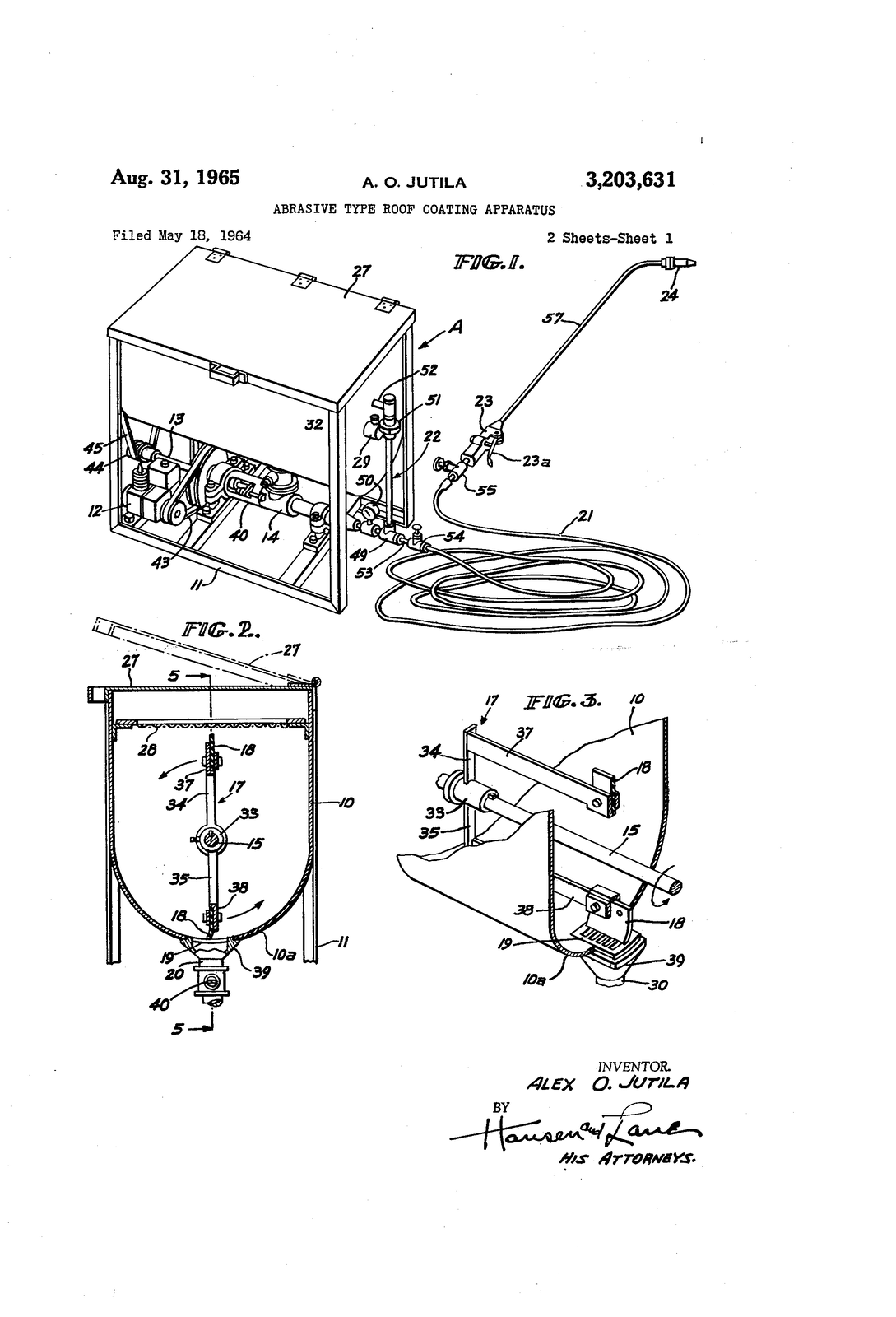
A plain hardwood base about 30 × 20 cm leaves room for the hose coil and a 1:6 figure with the wand. Add a small printed placard with the patent number — U.S. Patent 3,203,631, Alex O. Jutila — and a QR code linking to jetsprayproducts.com so visitors can read the story.
The patent itself is on this site as a PDF if you want to reproduce a drawing sheet on the placard.
Where the dimensions come from
The kit is generated from the parametric model by cad/tools/build_kit.py, so it can be re-run if better evidence turns up. Every dimension in the model carries its provenance: documented ones come from brochures, the patent, the service leaflet and Bob Ruth's shop notes; others are derived from those or estimated from photographs. No Jetspray machine is known to survive, so treat the estimates as estimates.