Service and Operating Instructions
The printed operating leaflet with a lettered parts legend and an exploded drawing. Uses the 6308 Riverdale St. address (later than El Cajon Blvd.).
About this transcription
Typeset/printed leaflet with halftone photographs and one exploded line drawing. Page 4 is printed rotated 90° on the sheet (landscape cover); described upright.
Transcriber's summary
- What it is: The Airless Jetspray (Pat. No. 3,203,631), Jetspray Products, Inc., 6308 Riverdale Street, San Diego, CA 92120, tel. (714) 283-7859. A portable, engine-driven, agitated-tank airless sprayer for heavy coatings (asphalt-base, heavy, fibered coatings are named).
- Flow path: Tank (with rotating agitator V) → bottom-center outlet (through removable outlet screen) → 1-1/2" 45° street elbow (L) → 1-1/2" no-hub coupling (M) → 1-1/2" companion flange (N) → pump (K) → discharge pipe → pressure gauge (O) → tee (38) → outlet valve (X/37) → hose connection (W) → hose → spray gun. From tee 38 a 3/4" riser (36 18" nipple, 35 union, 34 8" nipple, 33 reducer) goes up to the spring-loaded ball relief/bypass valve (S: 28 tee, 27 ball, 26 spring, 25 valve, 24 7/16" adjusting bolt); excess flow bypasses through the side of tee 28 → 3/4" nipple (30) through the tank wall with gaskets (29, 31) → 3/4" 90° elbow (32) back into the tank (return line P).
- Drive path: Engine (E) with governor speed adjustment (Z) → V-belt centrifugal/friction clutch (Q) engages with speed → pump drive belt (J) → 12" pump pulley (I) on the jack shaft (G) → universal coupling (H) → pump (K). Jack shaft supported by pillow block (F) at the pulley end; agitator driver V-belt (D) goes up to the 18" pulley (C) on the 1" agitator shaft via the 1" wheel hub (R); agitator shaft carried in agitator shaft bearings (T) on each tank end. Pulley guard (Y) covers the 18" pulley. (That a small pulley on the jack shaft drives belt D is inferred from label positions F, G, D; the leaflet does not state it explicitly.)
- Operation: Volume set by engine/pump rpm (governor Z); pressure set by relief valve S read on gauge O; machine recirculates (gun nozzle returned into tank / bypass) to mix coatings before spraying; continuous refill possible; clean with solvent then water daily.
- Numeric specs: Pat. 3,203,631; governor raised ≈1/2" to start; 18" pulley (C); 1" wheel hub (R); 12" pump pulley (I); 1-1/2" suction fittings (L, M, N); 7/16" pressure adjustment bolt (24); 3/4" nipple (30), 3/4" 90 elbow (32), 3/4" × 8" nipple (34), 3/4" union (35), 3/4" × 18" nipple (36). No pressures, flow rates, engine HP, tank capacity, or overall dimensions are given in this leaflet.
Page 1 of 4
Header:
AIRLESS JETSPRAY
Exclusive Pat. No. 3,203,631SERVICE AND OPERATING INSTRUCTIONS
Read instructions carefully before operating machine (underlined)HOW TO OPERATE JETSPRAY:
Warning: do not run pump when dry. Prime pump and hose before putting coating into machine. Priming is only necessary to keep pump and hoses clean for better coatings flow.
TO START :
- Check oil, proper lubrication, and gas in engine
- Release pressure adjustment valve (S) tension.
- Attach hose and spray-gun to tank outlet valve (X), which is located below pressure adjustment valve (S). Return spray-gun nozzle into tank. Open valve (X) to allow free return flow into tank. Be sure that tank has correct solvent.
- Raise governor adjustment (Z) approximately 1/2" ( engine speed increases as governor adjustment (Z) is raised higher. Volume output is determined by pump r.p.m.). Pull out choke. Machine is ready to start.
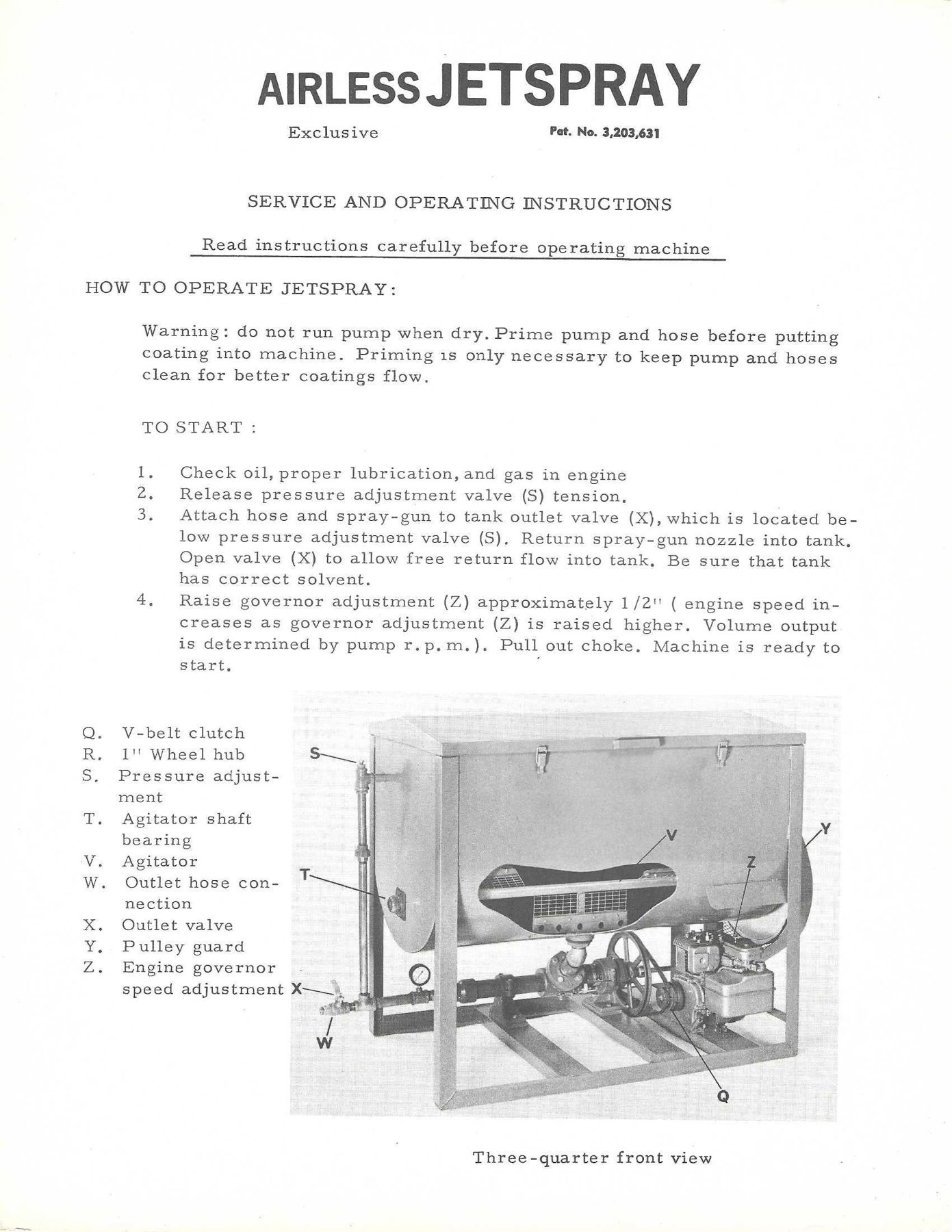
Legend (left of photo):
Q. V-belt clutch
R. 1" Wheel hub
S. Pressure adjustment
T. Agitator shaft bearing
V. Agitator
W. Outlet hose connection
X. Outlet valve
Y. Pulley guard
Z. Engine governor speed adjustment
Caption: Three-quarter front view
Photo (black & white studio photo, light-gray painted machine on white background) — description:
- Frame: Open rectangular cage of steel angle iron (light gray). Two rectangular end frames (vertical posts at each corner, top and bottom rails) joined by long bottom rails front and back, plus several (4–5 visible) flat cross slats across the base on which the pump and engine sit. The top of the frame front rail is flush with the tank lid line. The frame stands directly on the floor (no wheels visible).
- Tank: Long horizontal tank occupying the upper ~55% of the frame. Front face is flat sheet steel, top is a flat hinged lid with slightly overhanging edges, two over-center draw latches (hasps) on the front edge and a small rectangular handle in the middle of the front edge. Tank ends: the left end plate is visible as a rounded-bottom (semicircular) shape that projects past the frame end; the lower body is rounded. A cutaway window (photographic cutaway, irregular kidney/bean-shaped opening) in the front face reveals the agitator (V): a horizontal bar near the bottom with a perforated rubber wiper strip (row of round holes), two side-by-side wire-grid screens on the center blade, and further screens visible at the left and right ends (outside blades) on the upper side.
- Left end (outlet end): T = a square-flanged bearing on the end plate at about the agitator axis height (roughly mid-height of the rounded part). A vertical pipe riser runs up the left front corner outside the frame post: at the top, S (pressure adjustment valve) — a tee with a short horizontal nipple entering the tank end wall (bypass return); lower down a union in the riser. At the bottom, the riser meets a horizontal pipe in a tee; X = small lever-handle ball valve off the tee pointing left/out; W = outlet hose connection (male fitting) at the valve end.
- Under the tank: A pressure gauge (round dial, ~2–3" estimate) on a short stem on the horizontal discharge pipe. The horizontal discharge pipe runs right (with a pipe-saddle support on a pedestal) to the pump: dark painted body with a flanged connection; a short 45° elbow rises from the pump inlet up to the tank's bottom outlet (center of tank). Right of the pump: a bearing/coupling and the 12" spoked pulley (6 spokes), driven by a V-belt from a small pulley/clutch on the engine — Q = V-belt (centrifugal) clutch on the engine shaft.
- Engine: Small single-cylinder air-cooled engine (Briggs & Stratton style: finned cylinder head, recoil/blower housing, rectangular fuel tank on top/side) sitting on the base at the right end under the tank, with its output shaft facing the pump (toward the viewer's left). Z = engine governor speed adjustment (a small lever/linkage on top of the engine near the carburetor).
- Right end (pulley end): Y = pulley guard — a large round dish/drum-shaped cover on the right end of the tank, larger in diameter than the tank's rounded section, projecting outward.
Relative proportions (estimates from the photo, not stated): frame roughly as long as it is tall; tank body (lid to rounded bottom) ≈ 55–60% of frame height; 12" pump pulley ≈ 1/4 of the frame height → frame height on the order of 45–50" (estimate); engine height ≈ 1.3× pump-pulley diameter (≈ 15–16", consistent with a ~5 HP horizontal-shaft engine).
Page 2 of 4
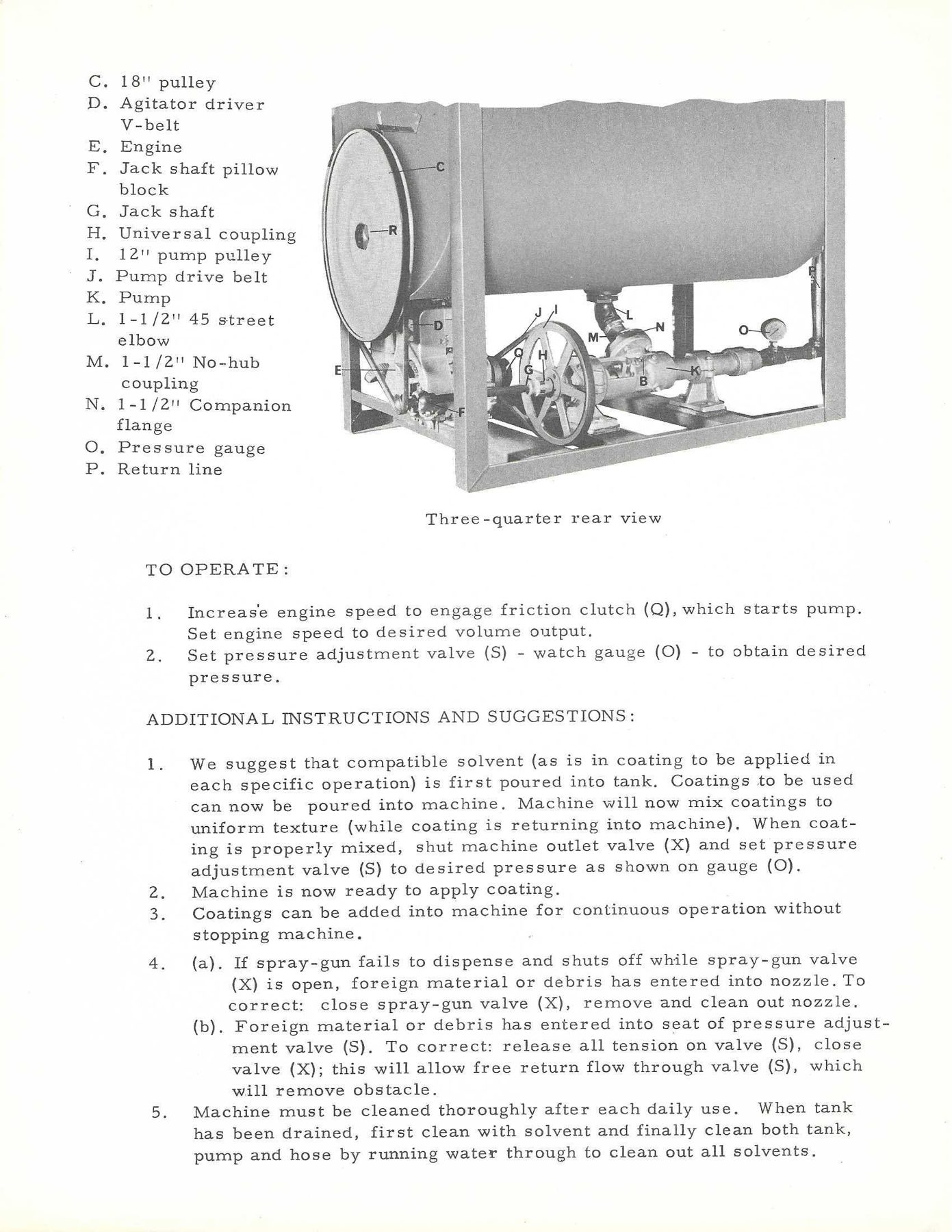
Legend (left of photo):
C. 18" pulley
D. Agitator driver V-belt
E. Engine
F. Jack shaft pillow block
G. Jack shaft
H. Universal coupling
I. 12" pump pulley
J. Pump drive belt
K. Pump
L. 1-1/2" 45 street elbow
M. 1-1/2" No-hub coupling
N. 1-1/2" Companion flange
O. Pressure gauge
P. Return line
(Note: labels A and B are not in the legend; a "B" label appears on the photo pointing at the pump body/bearing-bracket area between H and K. No "A" is visible.)
Caption: Three-quarter rear view
Photo description: Same machine from the rear-left. The photo's top edge is irregular/wavy (retouched/cropped), so the lid and upper tank are cut off; only the lower cylindrical-looking body shows.
- C (18" pulley): A large flat disc pulley (plain pressed-steel face, no spokes) mounted on the left end of the tank, nearly as tall as the visible tank end; R (1" wheel hub) at its center (hex/nut-like hub on the agitator shaft). Pulley guard removed in this view. A small bracket/tab protrudes from the frame top at the pulley's upper edge.
- D (Agitator driver V-belt): Runs from the lower left (engine/jack-shaft area) up around the 18" pulley.
- E (Engine): At lower left, under the tank at the pulley end, behind the frame end; its fuel tank/shroud visible.
- F (Jack shaft pillow block): At lower left on the base near the engine/frame end.
- G (Jack shaft): Horizontal shaft at the hub of the 12" pulley running toward the pulley end.
- H (Universal coupling): Between the 12" pulley hub and the pump.
- I (12" pump pulley): Large spoked (6-spoke) cast pulley standing vertically, center-left under the tank.
- J (Pump drive belt): V-belt from engine clutch (Q, labeled at the small pulley) up/over to the 12" pulley.
- K (Pump): Horizontal pump body with a long discharge pipe to the right, sitting on pedestal supports.
- L, M, N: The suction connection from the tank's bottom-center outlet down to the pump: L 1-1/2" 45° street elbow directly under the tank, M 1-1/2" no-hub coupling (rubber sleeve with clamps) in the vertical/angled drop, N 1-1/2" companion flange bolted to the pump inlet.
- O (Pressure gauge): Round gauge on a short tee/stem on the discharge pipe near the right (outlet) end.
- P (Return line): Vertical pipe at the far right rising along the tank's end (the riser to S).
- Frame: Angle-iron end frames and base rails; at least 3 base cross slats visible; pump and pulley pedestals mounted on slats.
Text:
TO OPERATE:
- Increase engine speed to engage friction clutch (Q), which starts pump. Set engine speed to desired volume output.
- Set pressure adjustment valve (S) - watch gauge (O) - to obtain desired pressure.
ADDITIONAL INSTRUCTIONS AND SUGGESTIONS:
- We suggest that compatible solvent (as is in coating to be applied in each specific operation) is first poured into tank. Coatings to be used can now be poured into machine. Machine will now mix coatings to uniform texture (while coating is returning into machine). When coating is properly mixed, shut machine outlet valve (X) and set pressure adjustment valve (S) to desired pressure as shown on gauge (O).
- Machine is now ready to apply coating.
- Coatings can be added into machine for continuous operation without stopping machine.
- (a). If spray-gun fails to dispense and shuts off while spray-gun valve (X) is open, foreign material or debris has entered into nozzle. To correct: close spray-gun valve (X), remove and clean out nozzle.
(b). Foreign material or debris has entered into seat of pressure adjustment valve (S). To correct: release all tension on valve (S), close valve (X); this will allow free return flow through valve (S), which will remove obstacle.- Machine must be cleaned thoroughly after each daily use. When tank has been drained, first clean with solvent and finally clean both tank, pump and hose by running water through to clean out all solvents.
Page 3 of 4
Text:
- Asphalt base coatings does thicken in colder temperatures. This condition can be corrected by adding compatible solvents to the coating. When using heavy or fibered coatings we suggest the outlet screen in the tank be removed to allow freer flow.
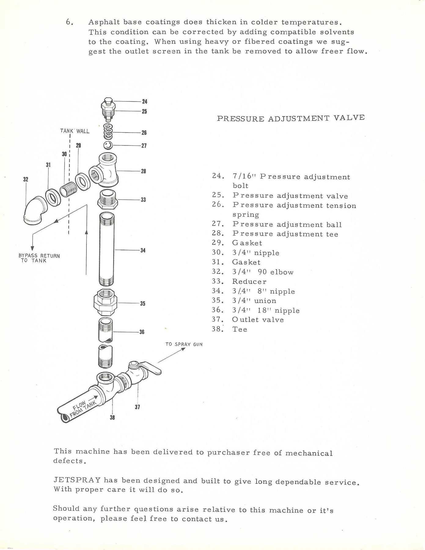
Exploded drawing — "PRESSURE ADJUSTMENT VALVE" (line drawing; vertical stack with a side branch):
From top to bottom along the vertical axis:
- 24 hex-head bolt (top), threaded into 25
- 25 valve body/seat: hex collar over a male-threaded body (screws into top of tee 28)
- 26 coil compression spring
- 27 ball
- 28 tee (female, vertical run; side outlet to the left)
- 33 reducer (hex bushing, male thread) below tee 28
- 34 pipe nipple (long; 8")
- 35 union (hex, two-piece)
- 36 pipe nipple (18"; drawn broken to show length)
- 38 tee at the bottom, horizontal run labeled "FLOW FROM TANK" (arrow, entering from lower left), branch up into 36
- 37 outlet valve (lever-handle ball valve) on the right end of tee 38, arrow "TO SPRAY GUN"
Side branch from tee 28 to the left (through a dashed vertical line labeled "TANK WALL"):
- 29 gasket (between tee 28 and tank wall, outside)
- 30 3/4" nipple (passes through the tank wall)
- 31 gasket (inside the tank wall)
- 32 3/4" 90° elbow (inside tank), arrow pointing down labeled "BYPASS RETURN TO TANK"
- An arrow runs up the riser (beside 34) indicating flow up toward the valve.
Parts list:
- 7/16" Pressure adjustment bolt
- Pressure adjustment valve
- Pressure adjustment tension spring
- Pressure adjustment ball
- Pressure adjustment tee
- Gasket
- 3/4" nipple
- Gasket
- 3/4" 90 elbow
- Reducer
- 3/4" 8" nipple
- 3/4" union
- 3/4" 18" nipple
- Outlet valve
- Tee
Closing text:
This machine has been delivered to purchaser free of mechanical defects.
JETSPRAY has been designed and built to give long dependable service. With proper care it will do so.
Should any further questions arise relative to this machine or it's operation, please feel free to contact us.
Page 4 of 4
(printed rotated; read upright)
Exclusive AIRLESS JETSPRAY Pat. No. 3,203,631
[photo]
JETSPRAY PRODUCTS, INC.
6308 RIVERDALE STREET
SAN DIEGO, CALIFORNIA 92120
Telephone (714) 283-7859
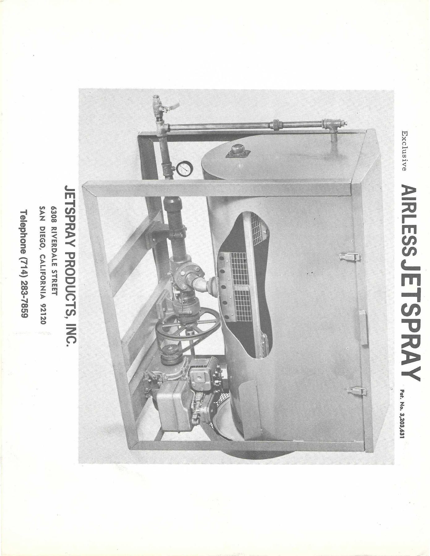
Photo: The same three-quarter front view as page 1, uncropped and larger (no letter callouts). Additional details visible:
- Lid: flat, slightly larger than the tank top, with two draw latches on the front edge and a flat handle centered between them; lid edges turned down.
- Tank front face is flat from the lid down to where it curves into the rounded bottom; the left end plate is clearly a U/D shape: straight vertical sides at the top that blend into a semicircular bottom. The bearing (T) is a 4-bolt square flange on that end plate.
- A rectangular sheet-metal flap/shield on the right lower front of the tank (near the pulley end, above the engine) — likely a belt guard/deflector (unlabeled).
- Return riser: tee with horizontal nipple into the end wall at top (S), a valve bonnet/adjusting bolt on top of S, a union about 1/3 down the riser, lower tee at floor level with lever ball valve (X) and hose fitting (W).
- Discharge pipe from the pump to the left: pump outlet → large-diameter pipe section (dark, ~1-1/2" to 2" estimate) with a pipe-clamp saddle on a pedestal → coupling → reducing down to ~3/4" pipe → tee with pressure gauge → lower tee of the riser.
- Pump: dark cast body with a 4-bolt companion flange on its inlet; inlet points up/back to the 45° elbow under the tank's bottom-center outlet; a shaft and coupling to the right toward the 12" spoked pulley; pump and pulley each on cast pedestal supports bolted to base cross slats.
- Engine: horizontal-shaft single cylinder with the drive (clutch pulley) facing left toward the 12" pulley; carburetor/governor linkage on top.
- Base: 4 flat cross slats visible spanning front-to-back between the bottom side rails.