Shop photographs
Forty-one Polaroids of machines and parts in the shop, three hand-written Polaroid backs, and two older black-and-white snapshots of earlier tank designs.
About this transcription
Pages 1–11 each hold three Polaroid (Polacolor 2) prints stacked vertically; page 12 holds four; page 13 shows the hand-written backs of three Polaroids; page 14 holds two older black-and-white snapshots. There is no printed text except what is noted. Colors are as rendered by faded Polaroid prints (strong cyan/green cast), so "dark green" paint may be dark green, dark gray, or black in reality — flagged where relevant. Photos are numbered top → bottom (page 12: TL, TR, BL, BR).
Cross-reference letters (C, D, … Z) and numbers (24–38) are from the printed service_instructions.md legend.
Transcriber's summary
- Scope: 41 Polaroids (shop build process, parts kits, close-ups), 3 annotated photo backs, 2 older B&W yard snapshots. They document the same machine as the printed leaflet: U-section trough tank with hinged lid in a full-height angle-iron cage frame; agitator on 1" stub shafts in 4-bolt square-flange bearings on each tank end; bottom-center outlet → 45° street elbow → no-hub coupling → companion flange → horizontal rotary pump (bearing bracket + packing gland + body with top inlet, axial discharge) on cast pedestals; 3/4" discharge line with gauge, tee, ball valve and hose fitting; vertical 3/4" riser with spring-ball relief valve returning into the tank end wall; Briggs & Stratton "5 HP" horizontal-shaft engine with V-belt clutch under the tank at the pulley end; 6-spoke 12" pump pulley; jack shaft with pillow block at the frame end; 18" white pressed-steel disc pulley on the agitator shaft; drum-shaped mesh-faced pulley guard.
- Not in photos: No overall dimensions, no tape-measure shots, no top/plan view, no clear view of the lid hinge, latches or lid stays (these are visible in the leaflet photos only), and no view of the belt routing for the agitator drive belt D from the jack shaft to the 18" pulley.
- Variants: Page 14 shows at least one earlier/variant build (round closed tank; teardrop belt guard), so not all photos depict the identical configuration; painted color varies (dark green/blue-green in shop Polaroids, light gray in the leaflet, light/silver in 10.2).
Page 1 of 14
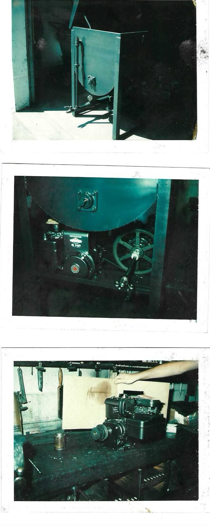
Photo 1.1 — Outlet end of a finished machine, lid open, in a doorway
Shows: A completed machine standing on a concrete floor in sunlight at a shop doorway, seen from the outlet (non-pulley) end, three-quarter. Painted a dark blue-green (Polaroid color). The tank end plate is clearly U/D-shaped: straight vertical sides for the upper part, blending into a semicircular bottom. The end plate sits just inside the angle-iron end frame (frame post visible at the right edge of the end plate, running full height to the floor). The lid is hinged at the back and raised nearly vertical; a lid stay strap is visible at the top. On the end plate: the 4-bolt square-flange agitator bearing (T) at about the center of the semicircle; the vertical return riser (P) running up the left edge of the end plate with a tee at the top that turns into the end wall (pressure adjustment valve S, bolt on top), a union about 1/3 down. At the bottom: a pressure gauge (round dial, upright on a stem), the horizontal discharge pipe running back under the tank to the pump (pipe clamp/saddle visible), and the lever-handle ball valve (X) with hose fitting (W) sticking out of the frame end toward the camera. Long side of tank (right of image) is a flat dark sheet with a folded top edge, flush with the frame post.
Photo 1.2 — End view under the tank: engine, 12" pulley, jack shaft
Shows: Close end view, lower half. The tank's semicircular bottom fills the top; the end plate carries a 4-bolt square-flange bearing (T) with the shaft end and set collar. Under the tank, left: a Briggs & Stratton horizontal-shaft engine (black), decal with B&S diamond logo and "5 HP" (reading most likely "5"; could conceivably be "8"), recoil/blower housing with red center emblem, carburetor/air cleaner at upper left. Right: the 6-spoke cast 12" pump pulley (I) standing vertically, its hub with a white-taped/plated coupling; a shaft (jack shaft G) runs from the pulley hub toward the camera to a pillow block (F) bolted on the base rail at the frame end. A V-belt runs from the engine area to the pulley rim. A frame post (angle iron) at right.
Photo 1.3 — Engine on the workbench
Shows: The engine (black Briggs & Stratton horizontal-shaft single, finned head, rectangular fuel tank/shroud on top) sitting on a heavy, oil-darkened workbench, output shaft toward the camera with a multi-groove clutch pulley (V-belt clutch Q) fitted. A man's hand/forearm rests on a cardboard sheet behind it. Shop wall with pipe wrenches, a hacksaw, files hanging. A small jar in front.
Scale: The hand (~7–8") vs engine: engine height ≈ 2 hand lengths → ~14–16" tall; footprint roughly 14" × 12" (estimates).
Page 2 of 14
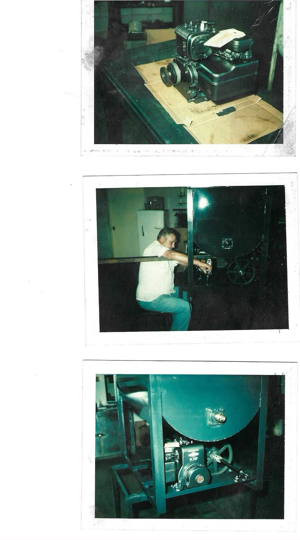
Photo 2.1 — Engine with clutch, on cardboard
Shows: Same black engine on flattened cardboard on a bench, three-quarter from the PTO side: clutch/pulley assembly (two-part: drum + pulley) on the shaft, cylinder fins top left, fuel tank right, a paper tag on the top. Mounting base visible.
Photo 2.2 — Man at the machine (scale reference)
Shows: An older, stocky man (white short-sleeve shirt, jeans) seated on a low stool beside the machine in a shop (white refrigerator and door in background), working with his hand on something under the tank. Right half: the machine end with the U-shaped end plate (light reflection at top), square-flange bearing near the bottom of the semicircle, and under it the spoked pulley and part of the engine. A horizontal steel bar/rail crosses in front at about his chest height (frame top rail or a separate bar).
Scale: Seated man's shoulder ≈ 40–45" above floor. The bottom of the tank's U is at about his shoulder/neck level; the tank end continues above the photo edge. Suggests tank bottom ≈ 28–36" above the floor and overall machine height ≥ 50" (estimates; perspective and stool height uncertain). The refrigerator (~5–5.5 ft) behind is further away.
Photo 2.3 — End view, engine/pulley/jack shaft, frame and stand
Shows: The machine from the end at a slight angle, sitting on (or next to) a low steel work stand (angle-iron frame at lower left). Tank end plate (U-shape, dark blue-green) with the square-flange bearing having a protruding shaft/collar. Under the tank: B&S "5 HP" engine (black, red emblem) at left; the spoked 12" pulley behind it; the jack shaft running toward the camera to a pillow block at the frame end. Tall frame post at the corner; the frame's bottom rails.
Page 3 of 14
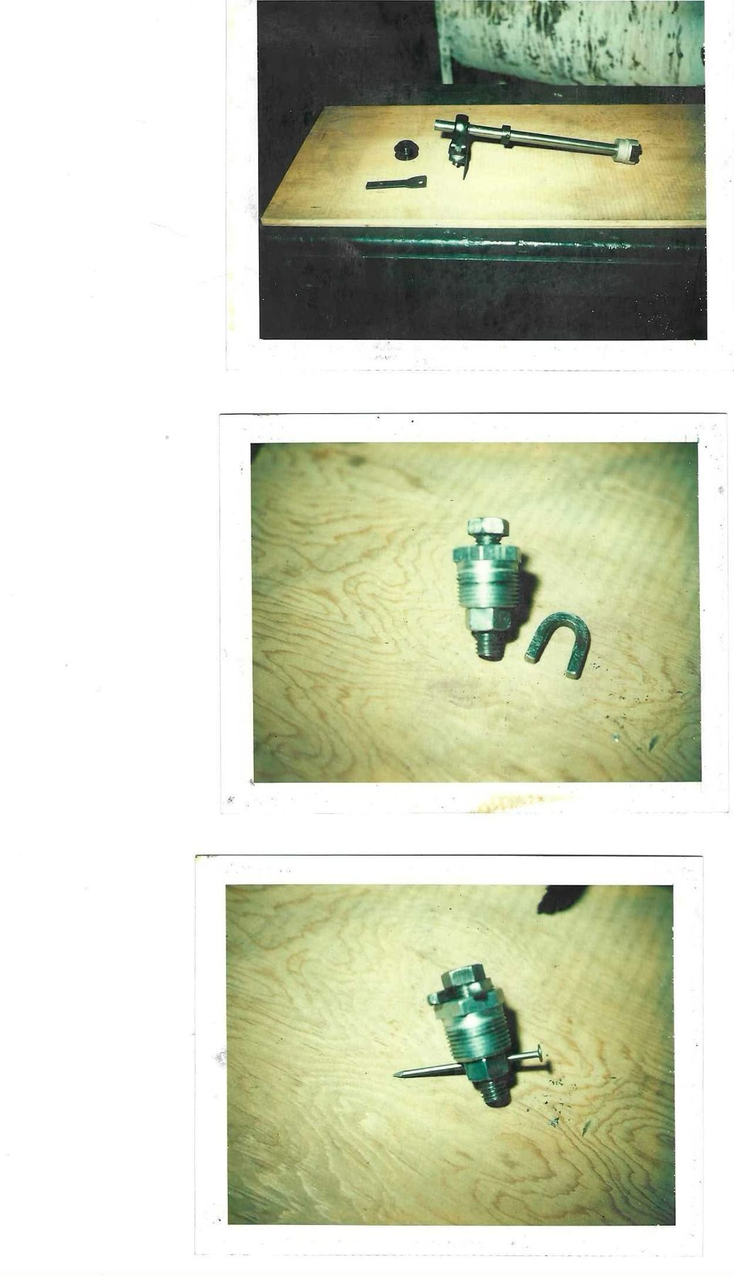
Photo 3.1 — Shaft sub-assembly on a board
Shows: On a plywood board in front of a dirty white cylindrical tank/drum: a steel shaft (~16–20" estimate) carrying a pillow-block-like bearing/clamp with a hanging bracket near the left, a set collar near the middle, and a white plastic/rubber jaw-coupling half on the right end; beside it a small black pulley/clutch disk and a short flat steel strap with a hole.
Photo 3.2 — Pressure adjustment valve (25) with bolt (24)
Shows: On plywood: the valve body — a hex collar on top, a large male pipe-threaded body (coarse threads, ~3/4"–1" NPT estimate), a hex below, and a smaller male-threaded nipple at the bottom; a hex-head adjusting bolt with a jam nut on top. Beside it, a small U-shaped (horseshoe) steel clip/bent rod.
Photo 3.3 — Same valve with a nail through a cross hole
Shows: The same valve body with a common nail inserted horizontally through a cross hole near the lower hex (demonstrating a cross-drilled passage or used as a stop/lock pin). A tab/lock washer under the top hex.
Page 4 of 14
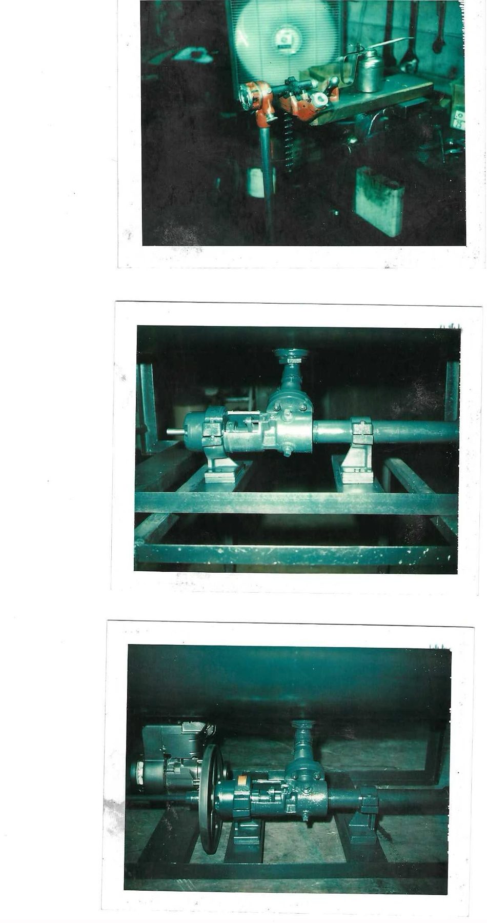
Photo 4.1 — Pipe threading
Shows: A red pipe threader / pipe vise (Ridgid-type) on a tripod stand with a pipe clamped, oil can on a board, shop fan behind. Process photo; no machine geometry.
Photo 4.2 — Pump on its pedestals in the frame (front)
Shows: Head-on view of the pump (K) mounted on the base of the frame (tank above, out of frame). Layout left→right: protruding drive shaft stub; a bearing bracket/housing on a cast pedestal foot; an open yoke (stuffing-box/packing gland region with gland bolts visible through the window); the pump body with a 4-bolt cover, a drain plug at the bottom and a vertical inlet neck rising from the top to a round flange (companion flange N) with a short stub; then the discharge pipe (large diameter, ~2" estimate) running right through a split pipe-clamp saddle on a second cast pedestal. Both pedestals sit on a flat plate bolted to base cross members. Frame: angle-iron base rails in two levels in the foreground; frame posts at left and right edges.
Photo 4.3 — Pump, 12" pulley and engine (side)
Shows: Same row from slightly further back, with the tank's dark underside along the top: from left, the engine (black, fins and housing), then the 12" spoked pulley standing vertically right next to the pump's shaft end, then the pump with the vertical inlet neck and flange, then the discharge pipe on its pedestal at right. Frame base rails and a plate under the units.
Page 5 of 14
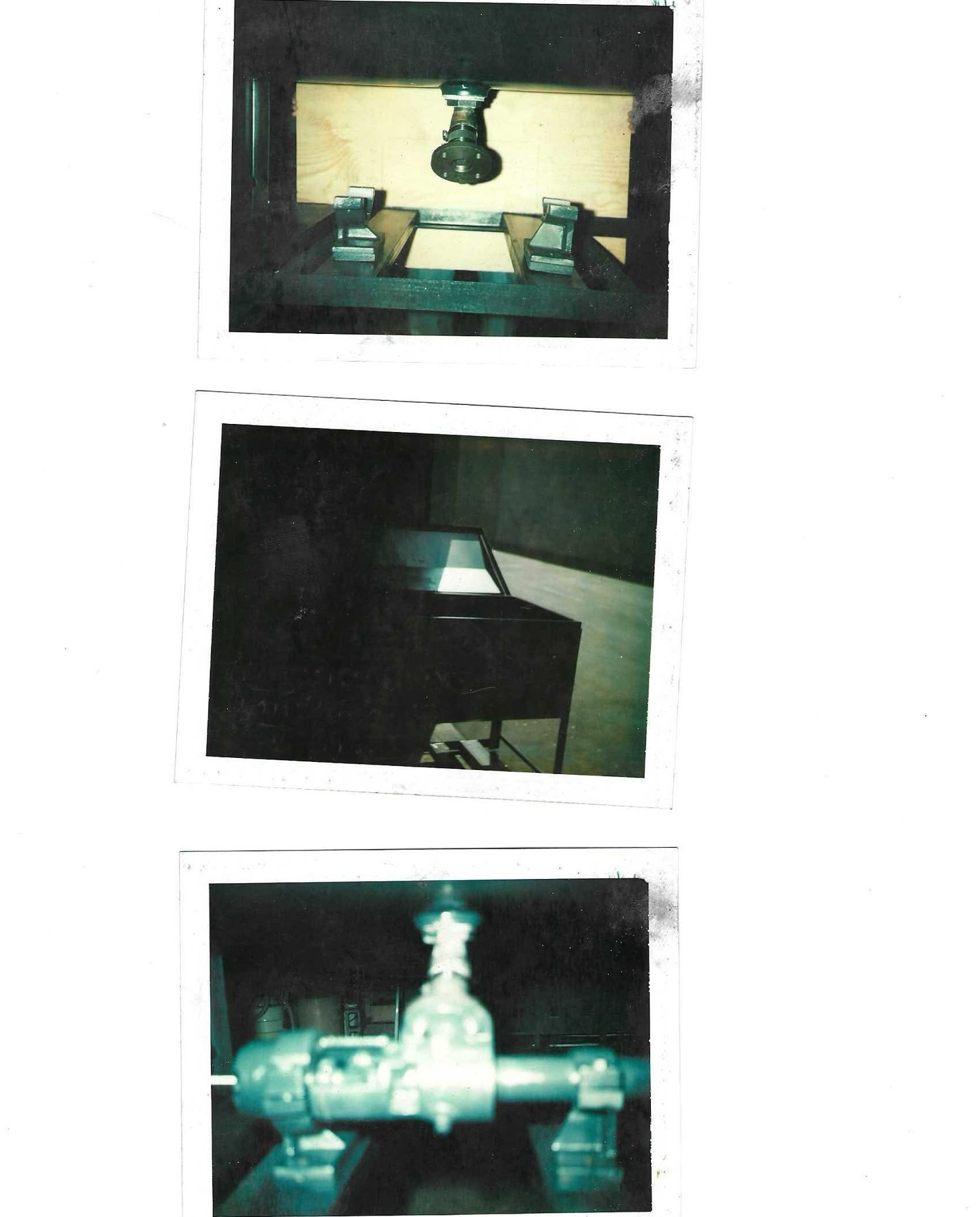
Photo 5.1 — Tank outlet and pump pedestals, viewed from the end
Shows: Looking along under the tank (a light plywood panel behind): from the tank bottom hangs the outlet stack — a hex bushing, short nipple/fitting, and a round 4-bolt companion flange (N) at the bottom. Below, on the base, two cast pedestal supports (bare, no pump fitted) bolted on the left and right base rails/slats; a rectangular sub-frame in the middle.
Photo 5.2 — Bare tank in frame (dark)
Shows: Very dark print: the tank/frame from a high end angle; the open top edge with the lid frame lit, side sheet, and the frame's lower cross members visible at the bottom.
Photo 5.3 — Pump on pedestals (blurred)
Shows: Out-of-focus view of the pump (same as 4.2): shaft stub left, bearing bracket on pedestal, body with vertical inlet neck and flange, discharge pipe on right pedestal.
Page 6 of 14
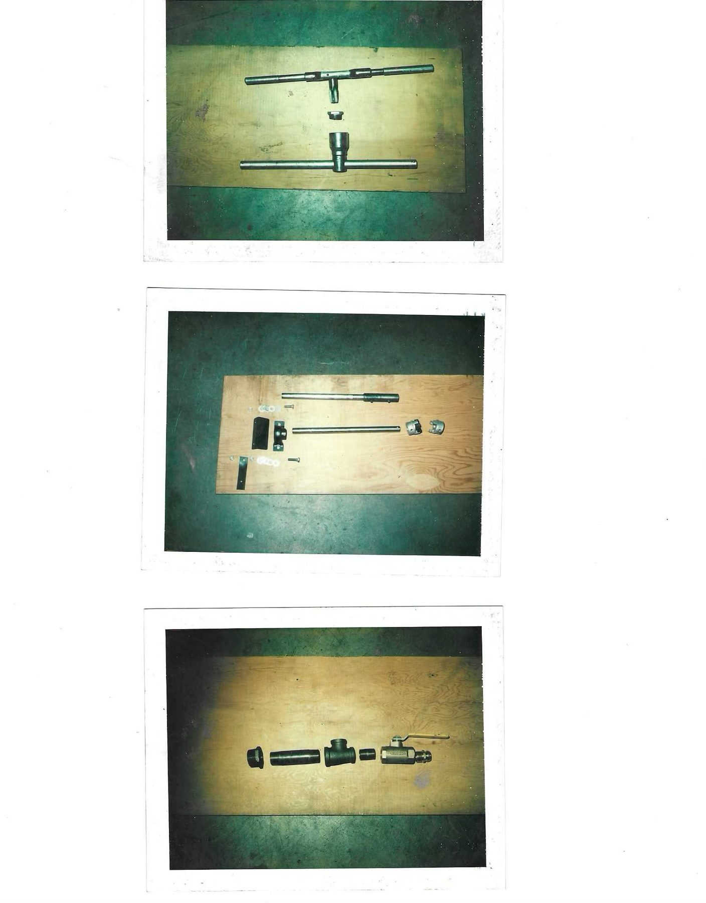
Photo 6.1 — Two T-handle tools / fittings
Shows: On plywood: (top) a long steel rod with a central T-body that has a short threaded square-ish stub pointing down and a collar on each side — a T-handle wrench/tool; (middle) a small hex plug/bushing; (bottom) a long round bar with a central deep socket pointing up — a T-handle socket wrench.
Photo 6.2 — Jack-shaft / coupling parts kit
Shows: Parts laid on plywood: a long steel shaft with a black tubular sleeve (coupler) on its right end carrying two set screws; a second plain shaft with a cross hole near its right end; two jaw-coupling halves (Lovejoy-type, with spider) at right; a pillow block bearing (cast housing with two bolt feet); a black bent sheet-metal angle bracket/guard; a flat strap with holes; bolts, nuts and washers.
Photo 6.3 — Outlet/discharge fittings
Shows: Left→right on plywood: a hex reducer bushing, a pipe nipple, a black-iron tee (38), a short close nipple, and a brass/plated lever ball valve (37 / X) with a yellow handle and a male hose fitting (W) on its outlet.
Page 7 of 14
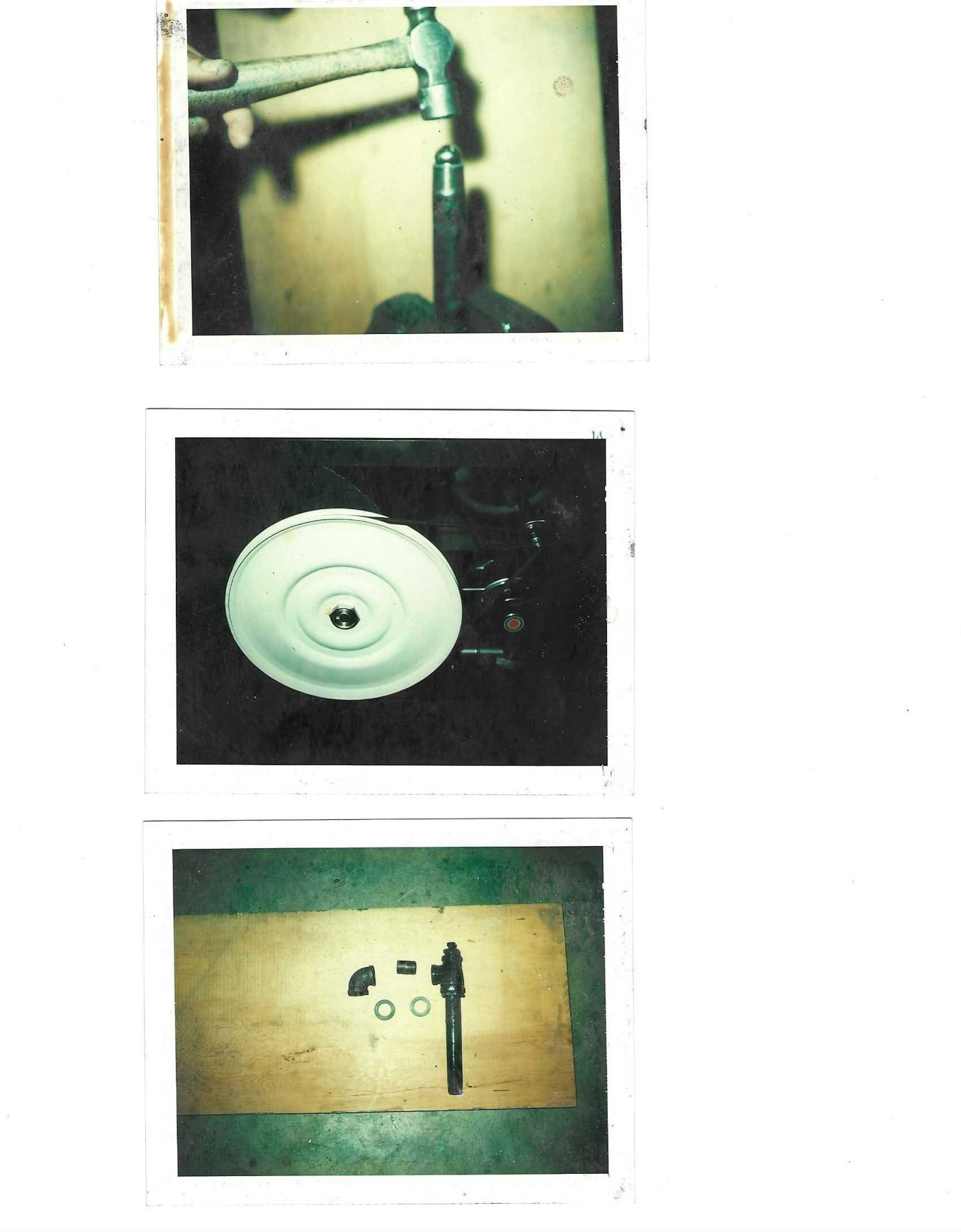
Photo 7.1 — Hammering a pin
Shows: A ball-peen hammer striking the top of a vertical steel pin/punch held in a vise against a plywood background (rivet mushrooming or pin driving).
Photo 7.2 — 18" pulley (C) on the tank end
Shows: The 18" pulley mounted on the pulley-end of the tank: a plain, pressed-steel disc pulley painted white/cream with concentric stamped rings, and a central hex hub/nut (wheel hub R) on the agitator shaft; the V-groove at the rim with a belt. Behind/below at right: the engine (red-dot emblem) and belt guard parts.
Photo 7.3 — Return-line (bypass) parts
Shows: On plywood: a black 3/4" 90° elbow (32), a short nipple (30), two white fiber gaskets (29, 31), and the pressure adjustment tee (28) with the valve body (25) screwed in its top, assembled onto a long vertical nipple (34) below it.
Page 8 of 14
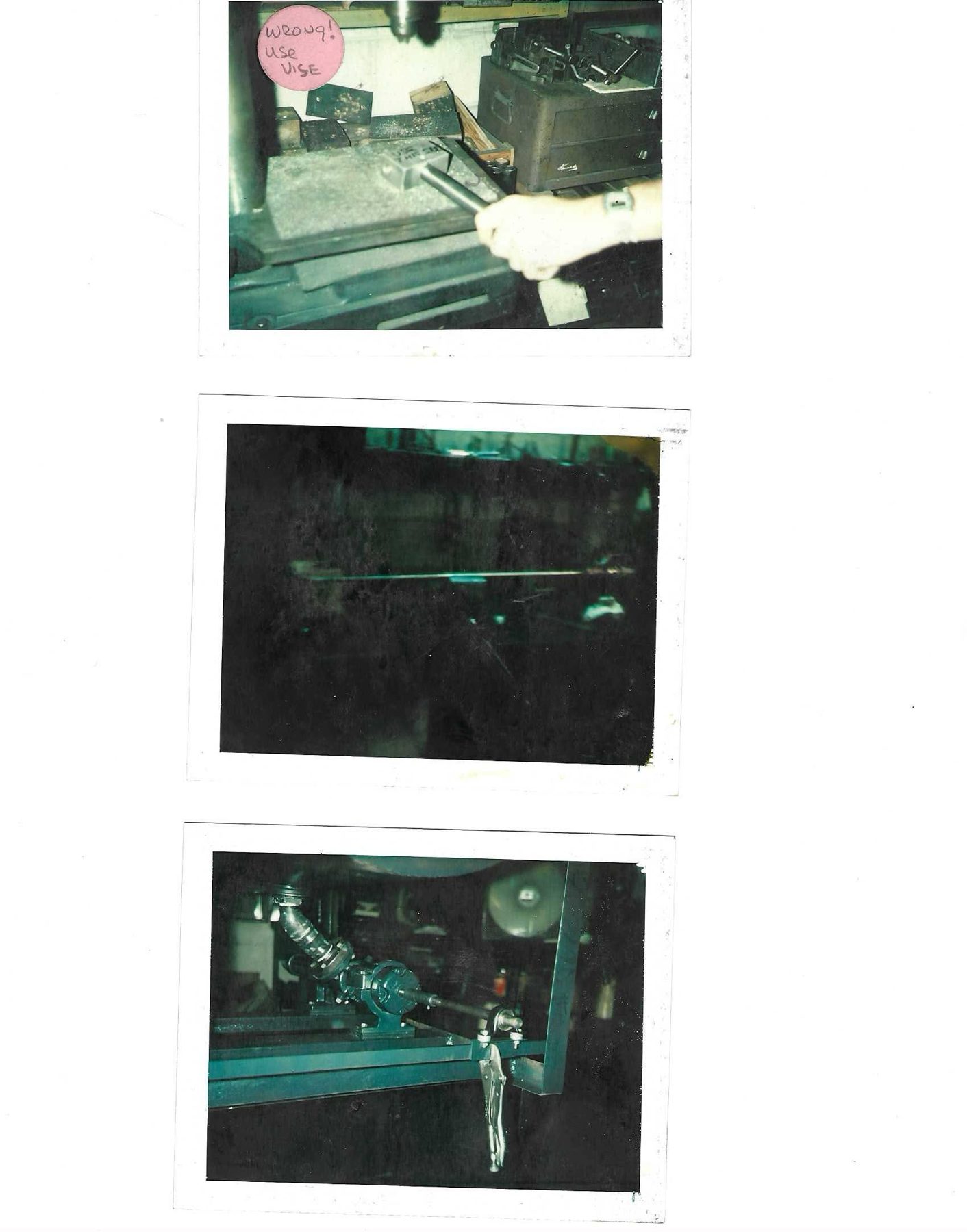
Photo 8.1 — Drilling a shaft, sticker "WRONG! use VISE"
Shows: A hand holding a 1" shaft in a drilling template block on a drill-press table without clamping; pink sticker "WRONG! use VISE". Tool chest and parallels behind.
Photo 8.2 — Dark, nearly blank
Shows: Very dark print: a horizontal rod/bar across the middle, possibly the agitator inside the tank. [Content largely indiscernible.]
Photo 8.3 — Suction drop, pump and jack shaft to frame-end pillow block
Shows: From the pulley end, low angle: from the tank's bottom (top left) a short nipple, a 45° street elbow (L) and a no-hub coupling (M, ribbed rubber sleeve with band clamps) slanting down to the pump inlet flange (N); the pump on its pedestal; a shaft running from the pump toward the camera/right to a pillow block sitting on a bracket at the frame end rail; a Vise-Grip locking plier clamping a bracket to the frame (fit-up in progress). The angle-iron frame end and base rails are visible; a fan in the background.
Page 9 of 14
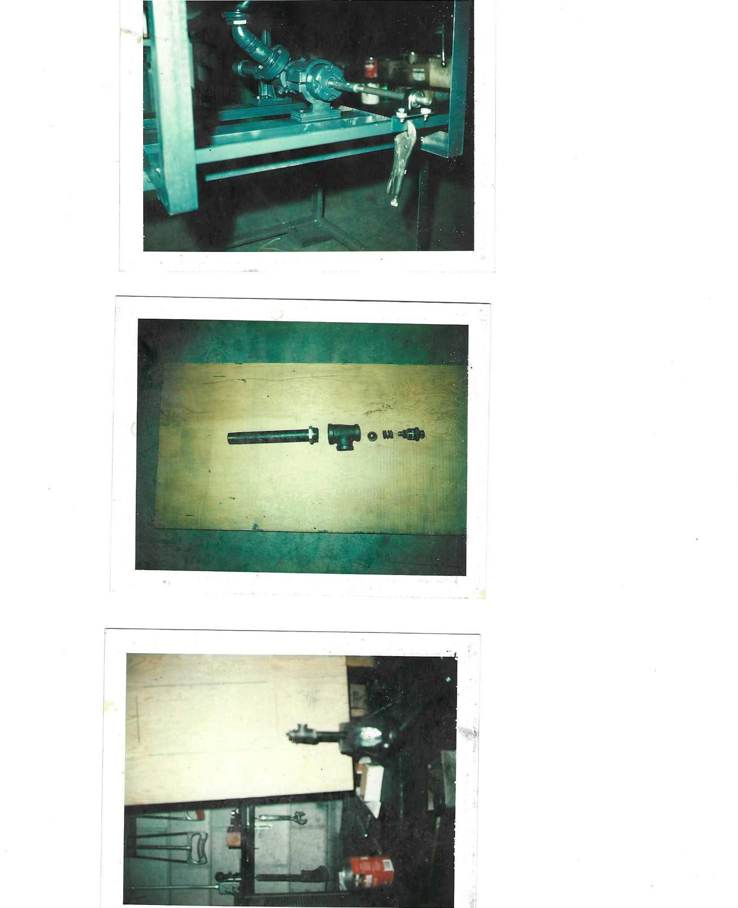
Photo 9.1 — Same drive area, wider
Shows: Similar to 8.3 from a slightly different angle, frame posts appear light/bare steel: the 45° elbow and no-hub coupling into the pump flange, pump on pedestal on base plate, shaft out to the pillow block on a bracket clamped with Vise-Grips at the frame end.
Photo 9.2 — Pressure adjustment valve parts, exploded
Shows: In a row on plywood: a pipe nipple with a hex reducer (33/34), the tee (28), a steel ball (27), a coil spring (26), and the valve body (25) with its bolt (24).
Photo 9.3 — Shaft in a vise (photo rotated 90°)
Shows: Printed sideways: a light plywood panel, and a short shaft with fittings held in a vise on a bench; pipe wrenches and a coffee can in the background.
Page 10 of 14
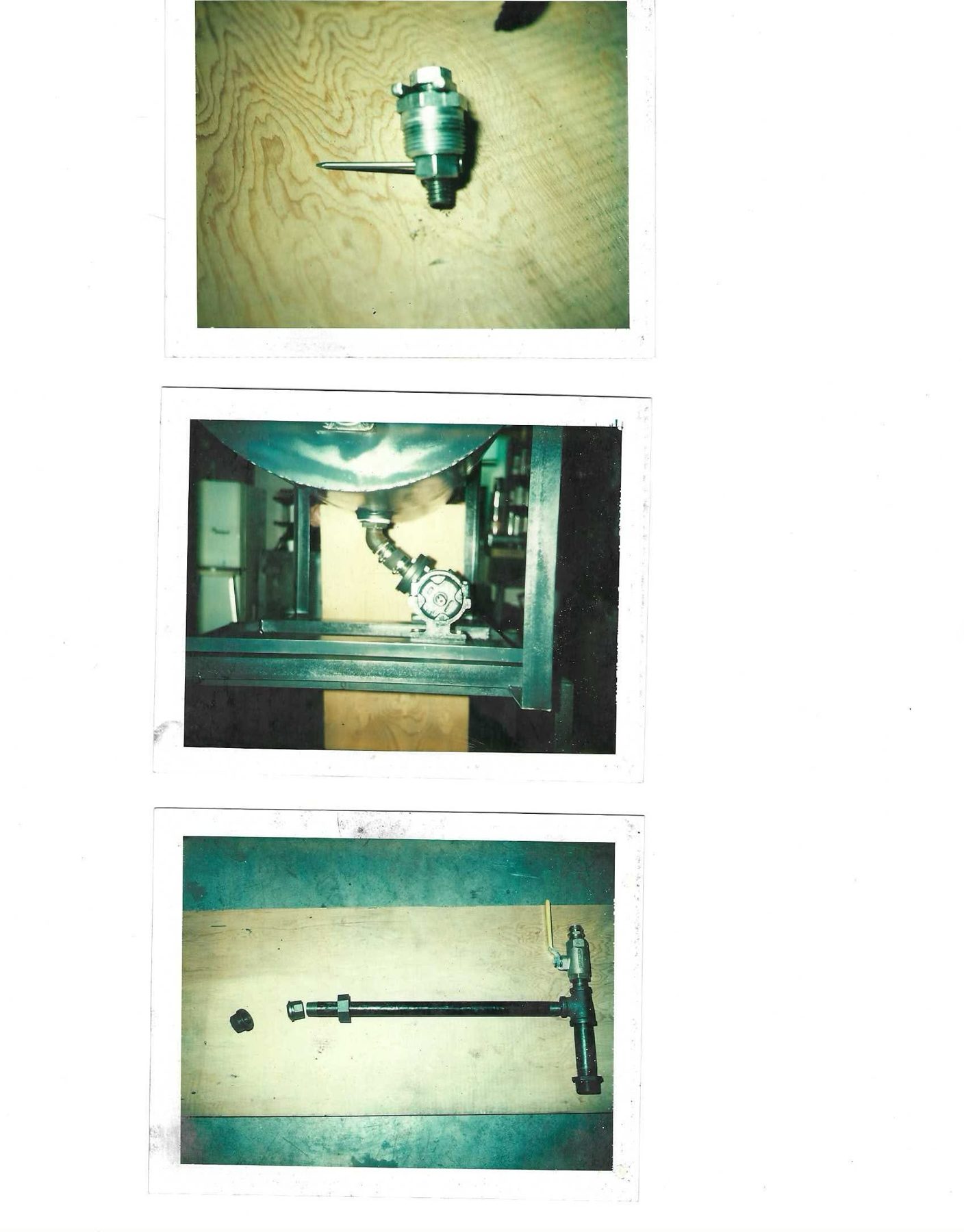
Photo 10.1 — Valve body with nail and tab washer
Shows: Valve body (25) with hex adjusting bolt and a tab/lock washer on top, a nail through its cross hole, threaded nipple at bottom.
Photo 10.2 — Under-tank view from the end (with refrigerator for scale)
Shows: View from the end under the tank, which is painted silvery/light here (different machine or primer): rounded tank bottom at top; from bottom center, a fitting, 45° elbow and no-hub coupling sloping down to the pump (round cover/flange end-on, on pedestal) on the base. Frame posts (angle iron) at both sides, base rails, a plywood sheet below the frame. A white refrigerator in the background at left.
Scale: The refrigerator (~5–5.5 ft tall, estimate) is behind the frame; the frame post height is similar to or slightly less than the fridge height visible — supports a machine height on the order of 4–5 ft (rough estimate, perspective uncertain).
Photo 10.3 — Discharge manifold sub-assembly
Shows: On plywood: (left, loose) a hex pipe cap/bushing and a reducer bushing; (assembled) a long black-iron nipple with a hex coupling near its left end (pump discharge side) running right into a tee; from the tee, a short nipple up to the ball valve (yellow lever) with hose fitting, and a short nipple down with a hex fitting.
Page 11 of 14
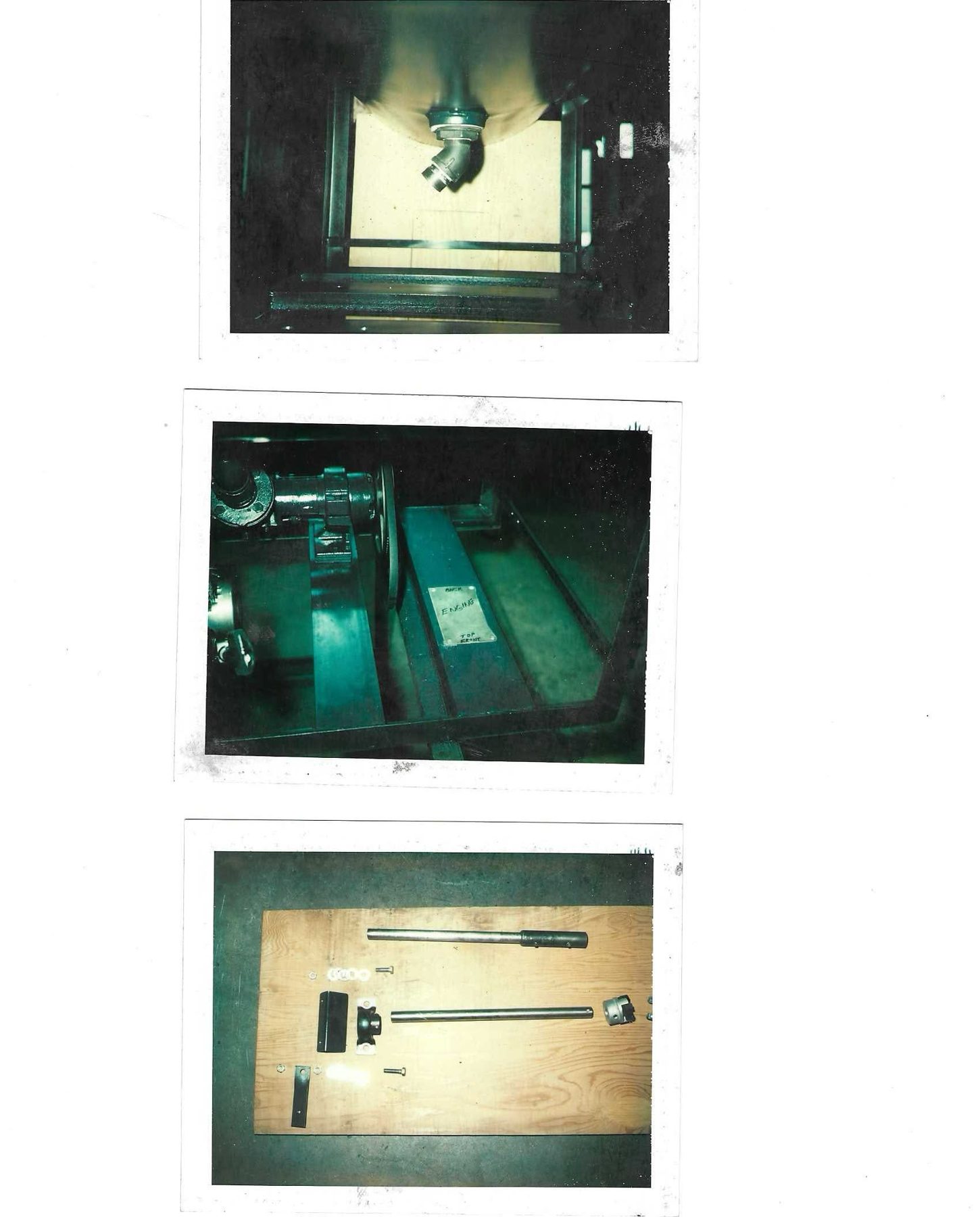
Photo 11.1 — Tank outlet from below
Shows: Looking up under the tank: the tank's rounded bottom (light tan/primer color) with a central outlet bushing (hex, the reducer bushing) and a 45° street elbow threaded into it, pointing down/sideways. Frame angle rails around; a cross brace bar below.
Photo 11.2 — Base with "ENGINE" mounting template plate
Shows: On a base cross member (flat steel bar) of the frame: a small steel template plate marked by hand "BACK / ENGINE / TOP FRONT" with holes at the corners. At left: the pump flange and bearing bracket on its pedestal, the edge of the 12" pulley, and part of the outlet-end plumbing. The base has several parallel flat bars/slats running across.
Photo 11.3 — Jack-shaft / coupling kit (again)
Shows: Same parts layout as 6.2: shaft with black sleeve coupler (two set screws), plain shaft with cross hole, pillow block, black bent bracket/guard, flat strap, jaw coupling half, bolts and washers.
Page 12 of 14
(four photos)
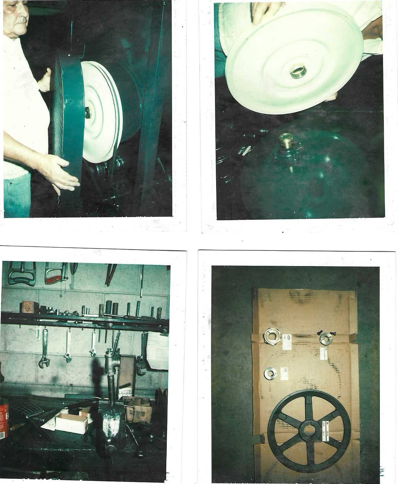
Photo 12.TL — Fitting the pulley guard (Y)
Shows: The older man (white shirt) holding the pulley guard in front of the 18" white disc pulley at the tank end. The guard is a shallow drum: a dark green sheet-steel band (rim, ≈ 3–4" deep estimate) with an expanded-metal mesh face on the outer side. Behind: the pulley with its V-groove, the belt going down, and the frame post.
Scale: Man's hand spans roughly 1/4 of the guard rim's visible height; guard diameter ≈ 20–22" (estimate; slightly larger than the 18" pulley).
Photo 12.TR — 18" pulley and hub, held up
Shows: The white pressed-steel 18" pulley held in someone's hands, center bore with a brass/plated threaded hub bushing; below, the green tank end (domed/disc surface) with a matching brass threaded hub (wheel hub R / reducer bushing) on the shaft end; at left edge the engine's "5 HP" decal visible upside-down.
Photo 12.BL — Shop bench with the riser assembly in a vise
Shows: A bench vise holding a vertical pipe with a tee and valve on top (the return riser with the pressure adjustment valve), boxes labeled "STOCKHAM" (valve/fitting manufacturer) on the bench, wrenches and saws hanging on a block wall, a coffee can.
Photo 12.BR — 12" pump pulley and bushings, new in box
Shows: On a flattened carton: a 6-spoke cast-iron V pulley (12" pump pulley I; single groove, hub with keyway) with a white product label on a spoke; above it three split taper/QD-type bushings and a hub/collar, each with a white label (text illegible).
Page 13 of 14
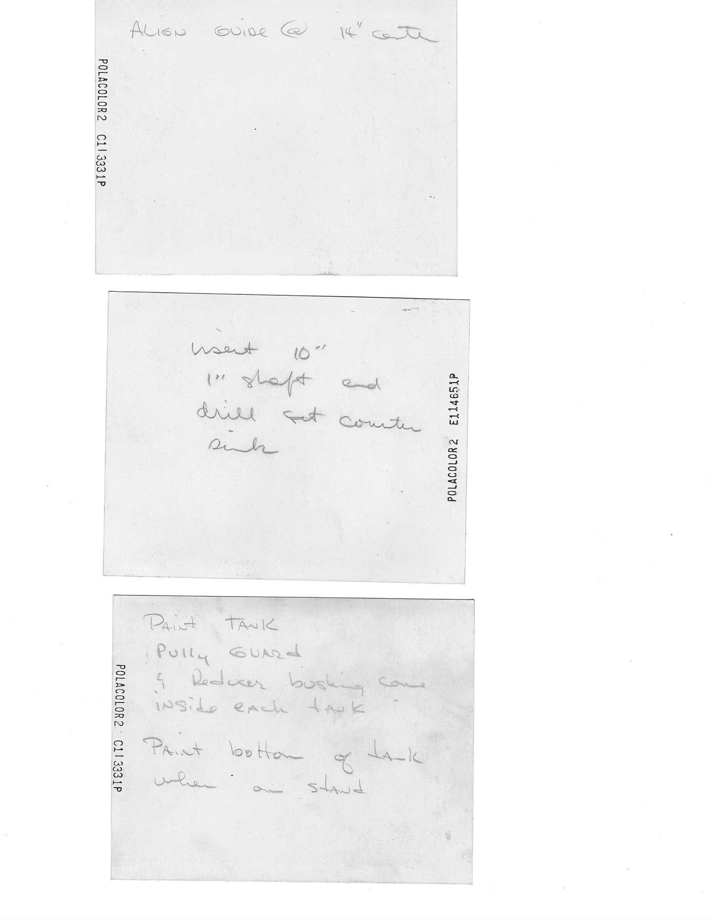
backs of three Polaroids (hand-written)
Each back carries a printed film code along one edge.
- Back 1: "ALIGN GUIDE @ 14" center" — film code "POLACOLOR 2 C11 3331P".
- Back 2: "Insert 10" 1" shaft and drill [
fostruck out] counter sink" — film code "POLACOLOR 2 E114651P". - Back 3: "Paint TANK / Pully GUARD / & Reducer bushing come inside each tank / Paint bottom of tank when on stand" — film code "POLACOLOR 2 C11 3331P".
Page 14 of 14
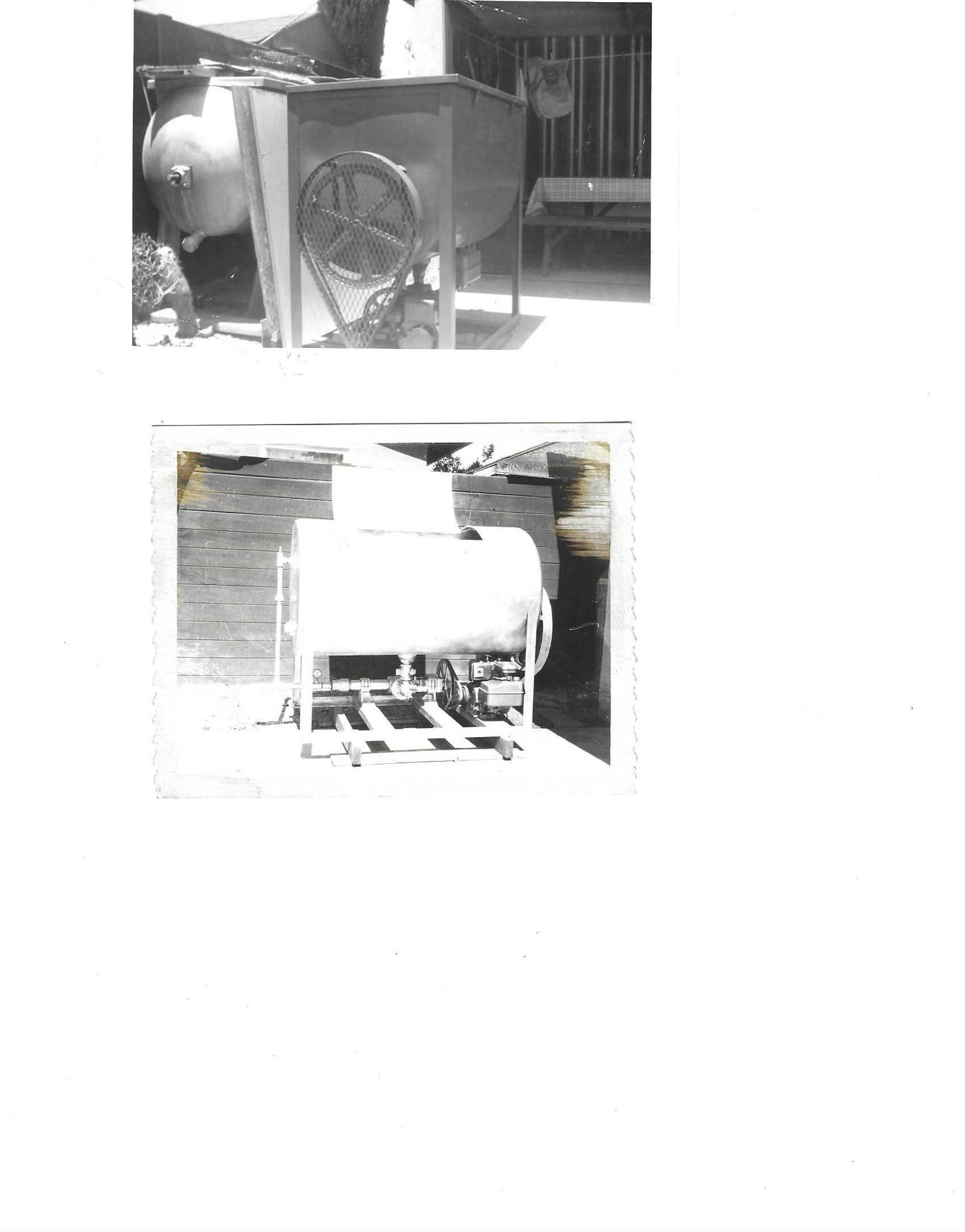
two older black-and-white snapshots
Photo 14.1 — Two tanks in a back yard (earlier design / variant)
Shows: Outdoors beside a house. Left: a fully closed horizontal cylindrical tank with domed/rounded ends (pressure-tank-like), a bearing/flange on its end, and a bottom fitting (drain) — mounted in a frame. Right/front: a Jetspray-type machine with the trough tank: an open-top rectangular box (flat sides, top rim) in a light-colored angle-iron frame whose posts go to the ground; on its end a teardrop-shaped expanded-metal belt guard enclosing the big spoked pulley at top and tapering down to a point near the base, where the belt goes to a lower pulley/pump; a cast pump/engine at the bottom. Light-colored paint. A clothesline and picnic table in background. A decal/lettering on the tank side (illegible).
Scale: Picnic table (~29–30" high) in the background vs the machine: the machine's top rim is roughly 1.5× table height → ≈ 4–4.5 ft (rough estimate, different distance).
Photo 14.2 — Prototype with cylindrical tank, against a wooden wall
Shows: Over-exposed snapshot of a machine with a horizontal cylindrical tank (with a rectangular raised box/hatch on top), mounted in a light-colored angle-iron end-frame; at the right end a large round pulley/wheel projecting beyond the tank end. Beneath: the bottom-center outlet dropping to a pump with gauge and horizontal discharge pipe running left to a vertical riser/return pipe at the left end; a spoked pulley and a small engine at the right under the tank. The base is a ladder of flat slats on two rails, and the whole machine sits on a separate rectangular skid/pallet frame of flat bars.