U.S. Patent 3,203,631
Alex O. Jutila's patent for the machine: two sheets of drawings (Figs. 1–6) and three pages of text.
Page 1 of 5
Uncorrected OCR text of page 1
Machine-read from the patent PDF; expect misread words.
Aug. 31, 1965 A. O. UTILA 3,203,631
 ABRASIVE TYPE ROOF COATING APPARATUS
 Filed May 18, 1964 2 Sheets-Sheet l.
 r 77/GA1. C
 24
 INVENTOR.
 4Zax O. M/7/Zea
 -tzu-'41 as arrowar2s.
Page 2 of 5
Uncorrected OCR text of page 2
Machine-read from the patent PDF; expect misread words.
3,203,631 A. O. JUTILA
 ABRASIWE TYPE ROOF COATING APPARATUS
 Aug. 31, 1965
 2 Sheets-Sheet 2 Filed May 18, 1964
 4ef w
 A.S. Arrowe'YS,
 INVENTOR
 aZAX O. u/77 a
 |
 SS
 BY
 27
 Sz: 2
 22 A. s
 7 ( 5.
 A4
 2
 R SS 22
 53
 S22
 e S
 SS
 Af02,
 aaaaaaaaaaaaa.
 <<<<<<<<<<<<<<<<<<<<= <!--ae (,,,,,,,=,<>)
 ::: ~~~~?~
Page 3 of 5
Uncorrected OCR text of page 3
Machine-read from the patent PDF; expect misread words.
United States Patent Office 3,203,631 Patented Aug. 31, 1965
 3,203,631 ABRASWE TYPE ROOF COATING APPARATUS
 Alex 0. utila, 5062 Zion, San Diego, Calif. Fied May 18, 1964, Ser. No. 368,155 3 Claims. (C. 239-124)
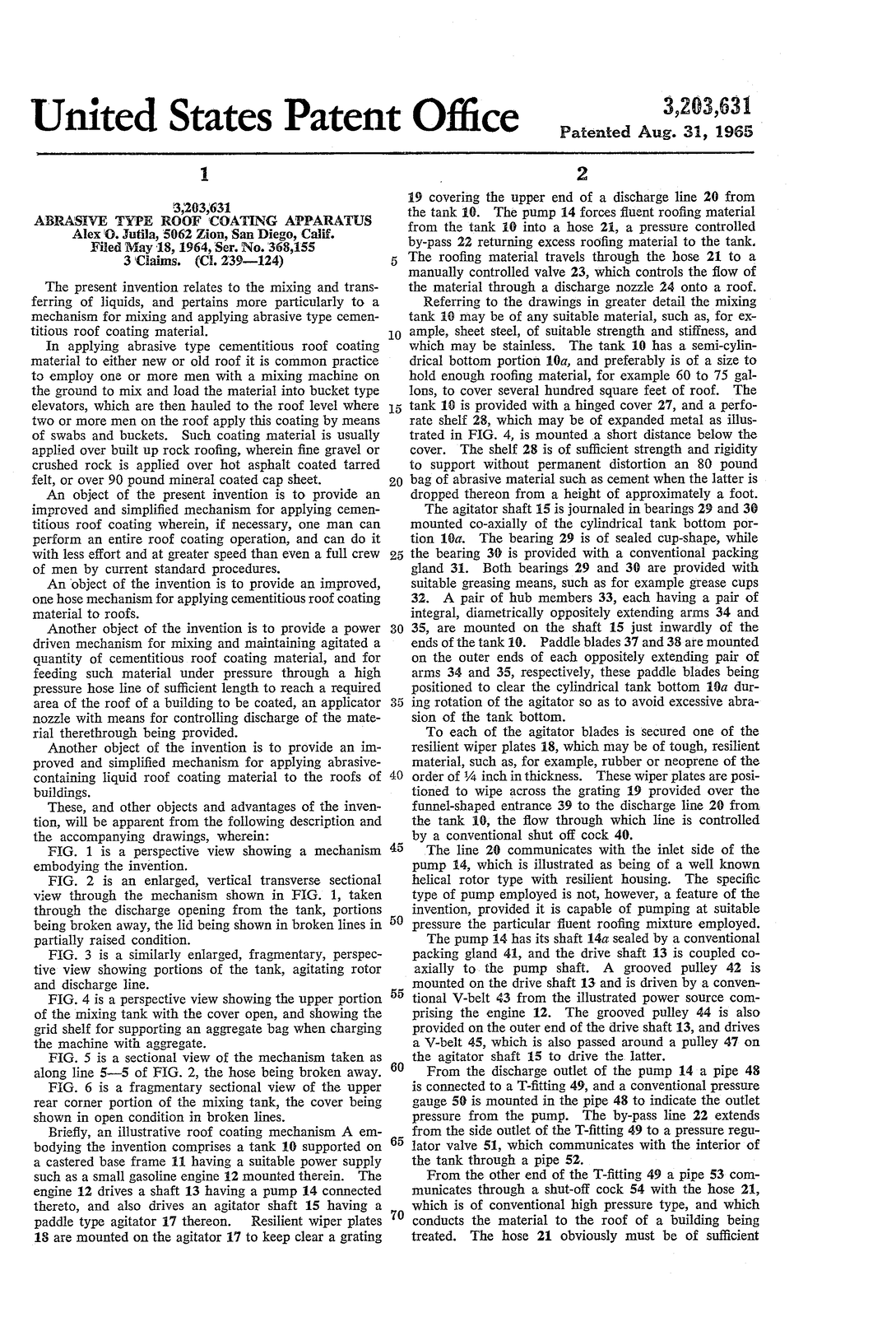
 The present invention relates to the mixing and trans ferring of liquids, and pertains more particularly to a mechanism for mixing and applying abrasive type cemen titious roof coating material. In applying abrasive type cementitious roof coating material to either new or old roof it is common practice to employ one or more men with a mixing machine on
 the ground to mix and load the material into bucket type elevators, which are then hauled to the roof level where two or more men on the roof apply this coating by means of Swabs and buckets. Such coating material is usually applied over built up rock roofing, wherein fine gravel or crushed rock is applied over hot asphalt coated tarred felt, or over 90 pound mineral coated cap sheet. An object of the present invention is to provide an improved and simplified mechanism for applying cemen titious roof coating wherein, if necessary, one man can perform an entire roof coating operation, and can do it
 with less effort and at greater speed than even a full crew of men by current standard procedures. An object of the invention is to provide an improved,
 one hose mechanism for applying cementitious roof coating
 material to roofs.
 Another object of the invention is to provide a power driven mechanism for mixing and maintaining agitated a
 quantity of cementitious roof coating material, and for feeding such material under pressure through a high pressure hose line of sufficient length to reach a required area of the roof of a building to be coated, an applicator nozzle with means for controlling discharge of the mate rial therethrough being provided.
 Another object of the invention is to provide an im proved and simplified mechanism for applying abrasive containing liquid roof coating material to the roofs of buildings.
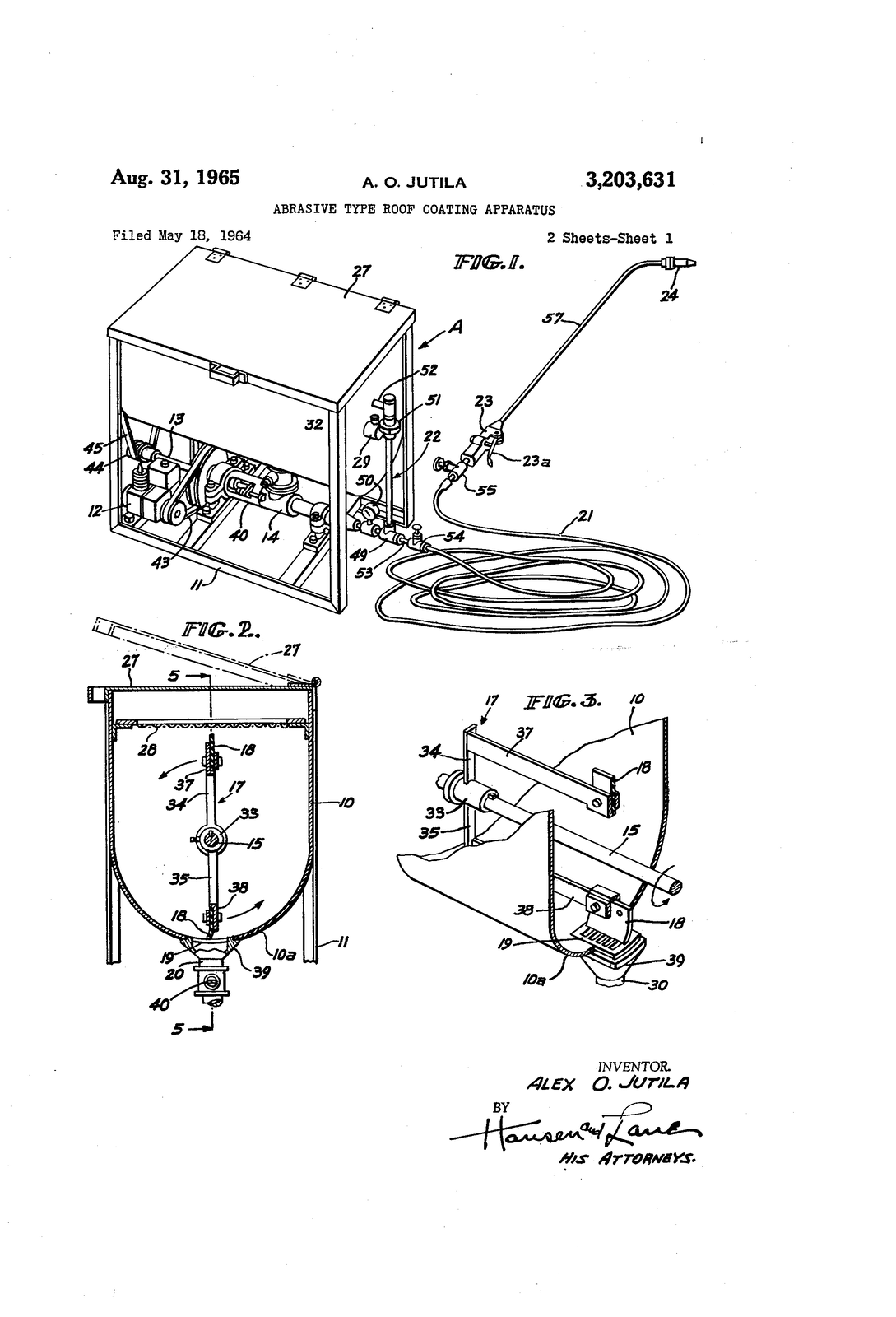
 These, and other objects and advantages of the inven tion, will be apparent from the following description and the accompanying drawings, wherein: FIG. 1 is a perspective view showing a mechanism embodying the invention. FIG. 2 is an enlarged, vertical transverse sectional view through the mechanism shown in FIG. 1, taken through the discharge opening from the tank, portions
 being broken away, the lid being shown in broken lines in partially raised condition. FIG. 3 is a similarly enlarged, fragmentary, perspec
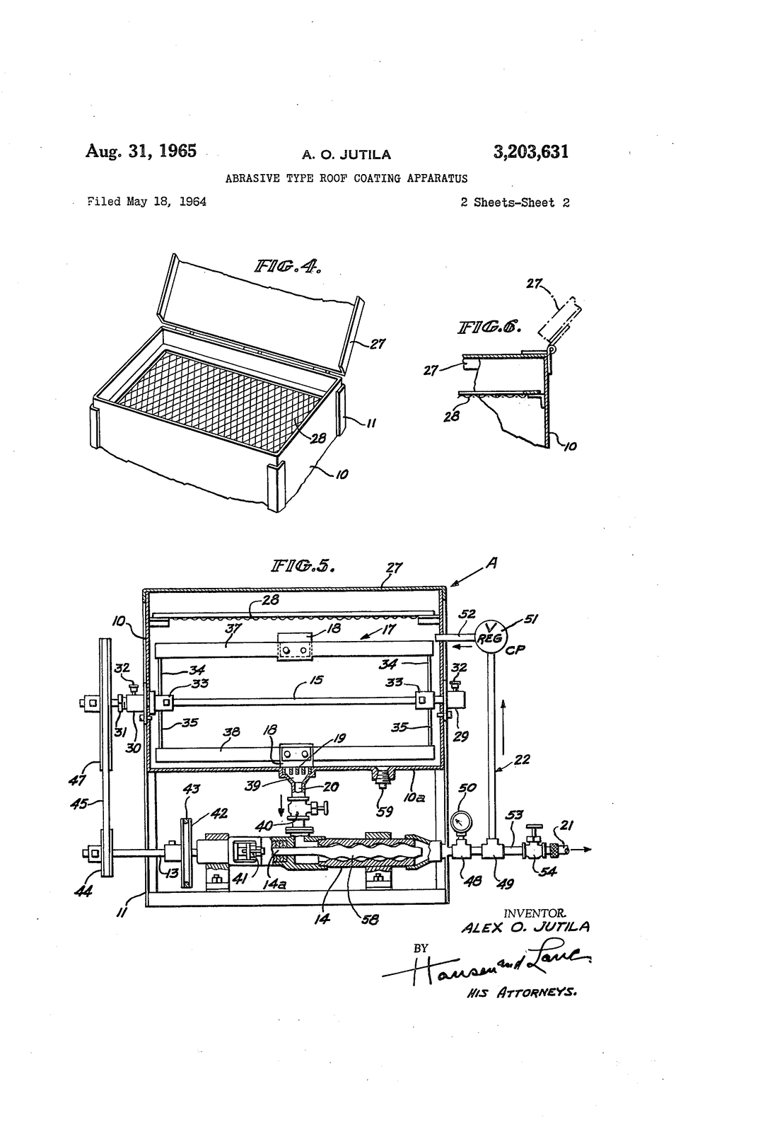
 tive view showing portions of the tank, agitating rotor and discharge line. FIG. 4 is a perspective view showing the upper portion of the mixing tank with the cover open, and showing the grid shelf for Supporting an aggregate bag when charging
 the machine with aggregate.
 FIG. 5 is a sectional view of the mechanism taken as
 along line 5-5 of FIG. 2, the hose being broken away. FiG. 6 is a fragmentary sectional view of the upper rear corner portion of the mixing tank, the cover being
 shown in open condition in broken lines. Briefly, an illustrative roof coating mechanism. A em bodying the invention comprises a tank 10 supported on a castered base frame 1 having a suitable power supply such as a small gasoline engine 12 mounted therein. The engine 12 drives a shaft 13 having a pump 14 connected thereto, and also drives an agitator shaft 15 having a paddle type agitator 17 thereon. Resilient wiper plates
 18 are mounted on the agitator 17 to keep clear a grating
 IO
 20
 25
 30
 35
 40
 50
 55
 60
 65
 70
 2
 19 covering the upper end of a discharge line 20 from the tank 10. The pump 14 forces fluent roofing material from the tank 0 into a hose 2, a pressure controlled by-pass 22 returning excess roofing material to the tank. The roofing material travels through the hose 21 to a manually controlled valve 23, which controls the flow of the material through a discharge nozzle 24 onto a roof. Referring to the drawings in greater detail the mixing
 tank it may be of any suitable material, such as, for ex ample, sheet steel, of suitable strength and stiffness, and which may be stainless. The tank 10 has a semi-cylin drical bottom portion 10a, and preferably is of a size to hold enough roofing material, for example 60 to 75 gal
 lons, to cover several hundred square feet of roof. The tank 10 is provided with a hinged cover 27, and a perfo rate shelf 28, which may be of expanded metal as illus
 trated in FIG. 4, is mounted a short distance below the
 cover. The shelf 28 is of sufficient strength and rigidity to support without permanent distortion an 80 pound
 bag of abrasive material such as cement when the latter is dropped thereon from a height of approximately a foot. The agitator shaft 5 is journaled in bearings 29 and 30 mounted co-axially of the cylindrical tank bottom por
 tion 10a. The bearing 29 is of sealed cup-shape, while the bearing 30 is provided with a conventional packing gland 31. Both bearings 29 and 30 are provided with suitable greasing means, such as for example grease cups 32. A pair of hub members 33, each having a pair of integral, diametrically oppositely extending arms 34 and
 35, are mounted on the shaft 15 just inwardly of the
 ends of the tank 10. Paddle blades 37 and 38 are mounted
 on the outer ends of each oppositely extending pair of arms 34 and 35, respectively, these paddle blades being positioned to clear the cylindrical tank bottom 10a dur ing rotation of the agitator so as to avoid excessive abra
 sion of the tank bottom.
 To each of the agitator blades is secured one of the resilient wiper plates 18, which may be of tough, resilient material, such as, for example, rubber or neoprene of the order of 4 inch in thickness. These wiper plates are posi tioned to wipe across the grating 19 provided over the funnel-shaped entrance 39 to the discharge line 20 from
 the tank 16, the flow through which line is controlled by a conventional shut off cock 40. The line 20 communicates with the inlet side of the
 pump 14, which is illustrated as being of a well known helical rotor type with resilient housing. The specific type of pump employed is not, however, a feature of the invention, provided it is capable of pumping at suitable pressure the particular fluent roofing mixture employed.
 The pump 14 has its shaft 14a sealed by a conventional packing gland 41, and the drive shaft 13 is coupled co axially to the pump shaft. A grooved pulley 42 is
 mounted on the drive shaft 13 and is driven by a conven tional V-belt 43 from the illustrated power source com prising the engine 12. The grooved pulley 44 is also
 provided on the outer end of the drive shaft 13, and drives a V-belt 45, which is also passed around a pulley 47 on the agitator shaft 5 to drive the latter. From the discharge outlet of the pump 14 a pipe 48 is connected to a T-fitting 49, and a conventional pressure gauge 50 is mounted in the pipe 48 to indicate the outlet pressure from the pump. The by-pass line 22 extends from the side outlet of the T-fitting 49 to a pressure regul
 lator valve 51, which communicates with the interior of the tank through a pipe 52. From the other end of the T-fitting 49 a pipe 53 com municates through a shut-off cock 54 with the hose 21, which is of conventional high pressure type, and which
 conducts the material to the roof of a building being treated. The hose 21 obviously must be of sufficient
Page 4 of 5
Uncorrected OCR text of page 4
Machine-read from the patent PDF; expect misread words.
3,203,631
 e
 as
 length to extend from the machine to all parts of a roof area to be coated.
 A second shut-off cock 55 is mounted on the other
 end of the hose 21, and is connected to the control valve 23, which, as illustrated, is of conventional, spring biased, grip-actuated type having a rigid tube 57 connected to its
 outlet end. The nozzle 24 on the outer end of the tube
 57 is of a type to discharge the material therefrom, pref erably in the form of a cone-shaped spray. The specific type of control valve and nozzle employed are not ma terial to the invention, and since numerous suitable valves and spray nozzles are available on the open market the details thereof are omitted.
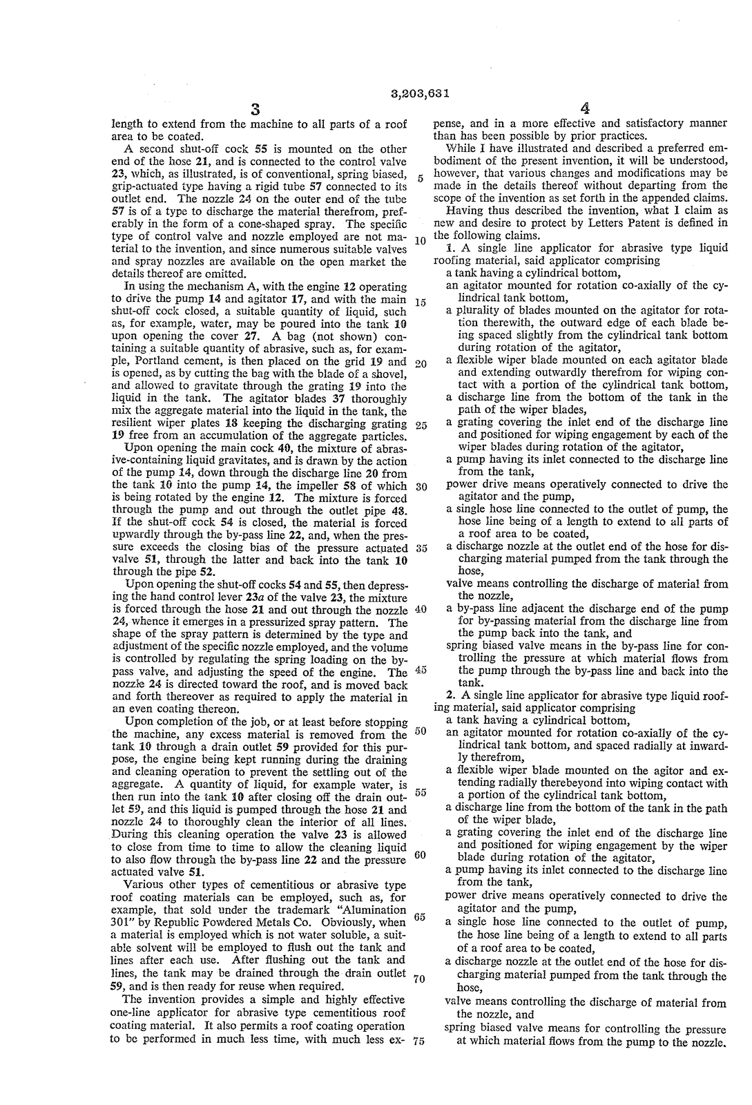
 in using the mechanism A, with the engine 12 operating to drive the pump 14 and agitator 17, and with the main shut-off cock closed, a suitable quantity of liquid, such as, for example, water, may be poured into the tank 0 upon opening the cover 27. A bag (not shown) con taining a suitable quantity of abrasive, such as, for exam ple, Portland cement, is then placed on the grid i9 and is opened, as by cutting the bag with the blade of a shovel, and allowed to gravitate through the grating 9 into the liquid in the tank. The agitator blades 37 thoroughly mix the aggregate material into the liquid in the tank, the resilient wiper plates 18 keeping the discharging grating
 19 free from an accumulation of the aggregate particles. Upon opening the main cock 49, the mixture of abras ive-containing liquid gravitates, and is drawn by the action of the pump 4, down through the discharge line 20 from the tank 6 into the pump 14, the impeller 58 of which is being rotated by the engine 12. The mixture is forced through the pump and out through the outlet pipe 48.
 if the shut-off cock 54 is closed, the material is forced upwardly through the by-pass line 22, and, when the pres sure exceeds the closing bias of the pressure actuated valve 51, through the latter and back into the tank 10 through the pipe 52.
 Upon opening the shut-off cocks 54 and 55, then depress ing the hand control lever 23a of the valve 23, the mixture is forced through the hose 21 and out through the nozzle 24, whence it emerges in a pressurized spray pattern. The shape of the spray pattern is determined by the type and adjustinent of the specific nozzle employed, and the volume is controlled by regulating the spring loading on the by pass valve, and adjusting the speed of the engine. The
 nozzie 24 is directed toward the roof, and is moved back and forth thereover as required to apply the material in an even coating thereon. Upon completion of the job, or at least before stopping
 the machine, any excess material is removed from the tank 10 through a drain outlet 59 provided for this pur pose, the engine being kept running during the draining and cleaning operation to prevent the settling out of the aggregate. A quantity of liquid, for example water, is
 then run into the tank 10 after closing off the drain out let 59, and this liquid is pumped through the hose 21 and nozzle 24 to thoroughly clean the interior of all lines. During this cleaning operation the valve 23 is allowed to close from time to time to allow the cleaning liquid to also flow through the by-pass line 22 and the pressure actuated valve 51.
 Various other types of cementitious or abrasive type roof coating materials can be employed, such as, for example, that sold under the trademark "Alumination 301” by Republic Powdered Metals Co. Obviously, when a material is employed which is not water solubie, a suit able solvent will be employed to flush out the tank and lines after each use. After flushing out the tank and
 lines, the tank may be drained through the drain outlet 59, and is then ready for reuse when required. The invention provides a simple and highly effective one-line applicator for abrasive type cementitious roof coating material. It also permits a roof coating operation
 to be performed in much less time, with much less ex
 O
 I5
 30
 40
 60
 65
 4.
 pense, and in a more effective and satisfactory manner than has been possible by prior practices. While I have illustrated and described a preferred em bodiment of the present invention, it will be understood, however, that various changes and modifications may be made in the details thereof without departing from the scope of the invention as set forth in the appended claims. Having thus described the invention, what I claim as new and desire to protect by Letters Patent is defined in the following claims. 1. A single line applicator for abrasive type liquid roofing material, said applicator comprising a tank having a cylindrical botton, an agitator mounted for rotation co-axially of the cy lindrical tank bottom,
 a plurality of blades mounted on the agitator for rota tion therewith, the outward edge of each blade be ing spaced slightly from the cylindrical tank bottom during rotation of the agitator,
 a flexible wiper blade mounted on each agitator blade and extending outwardly therefrom for wiping con tact with a portion of the cylindrical tank bottom, a discharge line from the bottom of the tank in the path of the wiper blades, a grating covering the inlet end of the discharge line and positioned for wiping engagement by each of the wiper blades during rotation of the agitator, a pump having its inlet connected to the discharge line
 from the tank, power drive means operatively connected to drive the agitator and the pump,
 a single hose line connected to the outlet of pump, the hose line being of a length to extend to all parts of
 a roof area to be coated, a discharge nozzle at the outlet end of the hose for dis charging material pumped from the tank through the hose, valve means controlling the discharge of material from
 the nozzle, a by-pass line adjacent the discharge end of the pump for by-passing material from the discharge line from the pump back into the tank, and spring biased valve means in the by-pass line for con trolling the pressure at which material flows from the pump through the by-pass line and back into the tank.
 2. A single line applicator for abrasive type liquid roof ing material, said applicator comprising a tank having a cylindrical bottom,
 an agitator mounted for rotation co-axially of the cy lindrical tank bottom, and spaced radially at inward ly therefrom, a flexible wiper blade mounted on the agitor and ex tending radially therebeyond into wiping contact with a portion of the cylindrical tank bottom, a discharge line from the bottom of the tank in the path of the wiper blade, a grating covering the inlet end of the discharge line and positioned for wiping engagement by the wiper blade during rotation of the agitator, a pump having its inlet connected to the discharge line from the tank,
 power drive means operatively connected to drive the agitator and the pump,
 a single hose line connected to the outlet of pump, the hose line being of a length to extend to all parts of a roof area to be coated, a discharge nozzle at the outlet end of the hose for dis charging material pumped from the tank through the
 hose,
 valve means controlling the discharge of material from
 the nozzle, and
 Spring biased valve means for controlling the pressure at which material flows from the pump to the nozzle.
Page 5 of 5
Uncorrected OCR text of page 5
Machine-read from the patent PDF; expect misread words.
3,203,681
 5 3. A single line applicator for abrasive type liquid roof ing material, said applicator comprising a tank having a cylindrical bottom a perforated shelf adjacent the top of the tank to re ceive and support a bag of abrasive material for mixing with liquid contained in the tank, an agitator mounted for rotation within the tank, below the shelf and co-axially of the cylindrical tank bottom, and spaced radially inwardly from the tank bottom, a flexible wiper blade mounted on the agitator and ex tending radially therebeyond into wiping contact with
 a portion of the cylindrical tank bottom,
 a discharge line from the bottom of the tank in the path of the wiper blade, a grating covering the inlet end of the discharge line and positioned for wiping engagement by the wiper
 blade during rotation of the agitator, a pump having its inlet connected to the discharge line
 from the tank, power drive means operatively connected to drive the 20 agitator and the pump,
 O
 5
 6
 a single hose line connected to the outlet of pump, the hose line being of a length to extend to all parts of a
 roof area to be coated, a discharge nozzle at the outlet end of the hose for discharging material pumped from the tank through
 the hose, valve means controlling the discharge of material from
 the nozzle, and spring biased valve means for controlling the pressure
 at which material flows from the pump to the nozzle.
 References Cited by the Examiner
 UNITED STATES PATENTS
 455,463 6/91 Pratt ----------------- 239-126
 2,580,551 1/52 Kacena --------------- 259-178
 2,596,074 5/52 Hawes --------------- 239-127
 2,618,576 11/52 Brown et al. ----------- 259-161
 2,880,976 4/59 True ----------------- 239-124
 2,976,025 3/61 Pro ------------------ 259-178
 EVERETTW. KIRBY, Primary Examiner.