Shop notes
Fifty pages of handwritten parts lists and step-by-step assembly procedures from the Jetspray shop, mostly on Winn Supply Co. notepads.
About this transcription
Pages 1–25
Pages were extracted as embedded JPEGs and read visually.
Conventions: [illegible] = unreadable; [word?] = uncertain reading; strikethroughs shown as text. Line breaks follow the original where practical. Spelling kept as written.
Transcriber's summary
Nature of these pages. Pages 1–25 are shop/assembly notes, not drawings or correspondence. Pages 1–2 are a handwritten parts list on plain paper; pages 3–25 are on Winn Supply Co. (subsidiary of Kaman Bearing & Supply Co.) notepads — 1675 Newton Ave, PO Box 1709, San Diego CA 92112 (233-5311) and 354 East Main St, El Centro CA 92243 (352-6460). Most are a numbered assembly-procedure series (circled 1–12, then 21–23, some unnumbered; 13–20 missing or later in the PDF). No dates, prices, customers or patent references appear. The only personal name is "Cathy" (p25). Brands named: Fafnir, Greenlee, Briggs & Stratton, Keystone No-Weld, V-Plex, WD-40.
What the machine is (per these pages). A portable, engine-driven tank sprayer: a tank on riveted legs with an internal paddle agitator, a pump bolted under/beside the tank fed from a bottom outlet, a belt drive through a jack shaft, and a ball-and-spring pressure-adjusting (relief) valve made from pipe fittings.
Subassemblies.
- Tank: rolled top lip; hinged lid pop-riveted (3/16" holes) (p12); legs/leg braces riveted through 1/4" holes centered in the lip, 1/4 x 1-1/2 (or 1-1/4) rivets, heads inside (p5, p11); bottom outlet with 1" Greenlee-punched center hole (p5).
- Agitator: 1" shafts, 12" and 10" (p8); Fafnir RCJC 1" flange bearing, "no substitute" (p7), bolted on with 7/16 x 1-1/4 bolts and 7/16 copper washers (p9); 4 x 7/16 + 1 x 3/8 holes on a "14" center" (p5); pitched blades, center blade over outlet (p9); rubber wiper on 10-24 (8-32) screws (p6); connecting pin 1/4" (1/8" pilot) about 1" from wall (p10); 2 x 1/4 x 1-3/4 bolts (p10); rotates "away from you" (p7).
- Screens: 11 x 2 bars with prongs (p6); a 9 x 9 screen with punched center hole (p14).
- Outlet/plumbing: 1-1/2 street ell, 3-1/2 nipple cut in half, companion flange, 1-1/2" 3-ply hose, two 32H clamps (p15–17); parts list p1–2.
- Pump: feet on spacers, 4 x 3/8 x 2" bolts to tank brace; companion flange 1/2 x 2" bolts with rubber gasket; must be square to engine (p16–19); 3/4" shaft with 1-3/4 x 3/16 key (p23).
- Drive: 5 HP Briggs & Stratton engine, 4 bolts 1-3/4 x 5/16 (p1, p24); V-Plex clutch on engine shaft, 3/16" key, two set screws (p25); V-belt "3460" (p24); jack shaft on 3/4" pillow blocks, 5/16 x 1-1/4 right and 5/16 x 1 left bolts, 3–5 shim washers, thrust collar toward pump (p1, p21); cast-iron pulley with 3/4" bore bushing (p20); pulley guard and pulley brace (p1); universal coupling (p1); steel hub numbers 37866 / 37776 / 37322 (p1).
- Pressure adjusting valve (p3–4): 1" x 3/4" x 3/4" tee; 3/4" x 8" nipple with a filed-flat top as the seat, in a 1" x 3/4" reducer bushing cut to 3 threads; 7/8" stainless ball and spring; 7/16 x 2" adjusting bolt in a drilled and tapped 3/4 x 1/8 steel bushing, set 3/16" from top, nut, drilled and pinned. Set "until valve just rattles".
Other numbers: set-screw spots drilled 7/32" (p20, p19); service fill 1/2 pint gas, 1 pint oil (p24).
Pages 26–50
Each page was viewed from its embedded scan image. Conventions: [illegible] = unreadable word; [word?] = uncertain reading. Line breaks follow the original where practical.
Transcriber's summary
What these pages are. All 25 pages (26–50) are handwritten shop instructions on Winn Supply Co. letterhead (Winn Supply Co., subsidiary of Kaman Bearing & Supply Co., "Specialists in Material Handling, Power Transmission"; 1675 Newton Ave / PO Box 1709, San Diego CA 92112, ph. 233-5311; 354 East Main St, El Centro CA 92243, ph. 352-6460). Pages 26–49 are one person's pencil cursive; p. 50 is a neater block-capital rewrite of the valve procedure by a different hand, and it mentions shop locations ("tool chest next to drill press", "bin below tool chest"). The pages do not name Jetspray, Jutila, a customer, a price or a date. The letterhead is the only place/name information.
What the machine is, from these pages. An engine-driven, belt-driven sprayer unit. A small engine sits on a tank support (p. 26). It drives a clutch pulley (the engine has a clutch), which belts to a pulley on a jack shaft. A universal coupling with a rubber spider connects the jack shaft to the pump (pp. 28–29). An agitator shaft with its own TRU-RUN pulley and belt runs off a bottom pulley (pp. 30–32), which points to an agitated tank. A pulley guard is riveted on (pp. 33–35). The pump outlet goes through a reducer, a tee and an 18" pipe to a ball valve and a hose adapter (pp. 36–39, 47–49). A home-made spring-loaded ball pressure adjustment (relief) valve returns flow into the tank through a gasketed hole in the tank top (pp. 40–48, 50).
Major subassemblies: engine mount; clutch/belt drive; jack shaft and universal coupling to the pump; agitator drive; pulley guard; pump outlet manifold; pressure adjustment valve; tank penetration. Upper and lower assemblies are painted and then joined at a union (p. 49).
Numeric specs (page refs)
- Engine mount: 3/8" holes ×4; 1 3/4 × 5/16" bolts, 5/16" lock washers and nuts (p. 27). Belt sits 1/2 way up the clutch (p. 26).
- Pulley set screw: 7/32" Allen (p. 28). Shaft countersink: 7/32" drill, 1/16" deep (p. 32).
- Coupling: Gerbing G-100, 3/4 (p. 28). Pump to brace: 5/16 × 1" bolt (p. 29).
- Agitator: 1/4" square key stock, 1/4" × 1" (p. 30). TRU-RUN (Gates) parts: 1" steel hub #37866 (p. 30), steel rim #37776, 1 3/4 steel pulley #37322 (p. 31).
- Pulley guard: holes at 1 3/4" in at the top; 8" and 4" along the edge from bottom center, 1 1/2" in; teardrop outline sketch (p. 33). 3/16" holes ×3; L brackets with 10-24 × 3/4 bolts and #10 lockwashers (p. 34); 3/16" pop rivets ×4 (p. 35).
- Outlet: 7/16" hole tapped 1/4" pipe thread in the reducer coupling (p. 36); 1 1/4→1" reducer bushing, 1 × 4 1/2" nipple, 1 × 3/4 × 3/4 tee (p. 37); 3/4" close nipple, 3/4 ball valve, 3/4 male-to-male hose adapter (p. 38); 3/4 × 18" pipe with a 3/4" union (p. 39).
- Pressure valve: 3/4 × 1/8 forged steel bushing, drilled .386 ("U") and tapped 7/16-14 NC; 7/16 × 2 bolt threaded to the head (p. 40). #29 drill (.136) for a nail pin, 1/16" left on each side (p. 42). 3/4 × 8" nipple (p. 43). 1 × 3/4 reducer cut ~3 threads and re-tapped 3/4 × 14 (p. 44). 7/8" stainless ball and spring in the tee (p. 50).
- Tank hole: 3/8" pilot, then enlarged with a Greenlee punch to 1 1/8" dia. (p. 47). Gasket 1" ID × 1 1/2" OD × 3/16" thick; 3/4" 90° elbow (p. 48).
No pressure, flow, speed, temperature, horsepower or tank volume appears on these pages.
Page 1 of 50
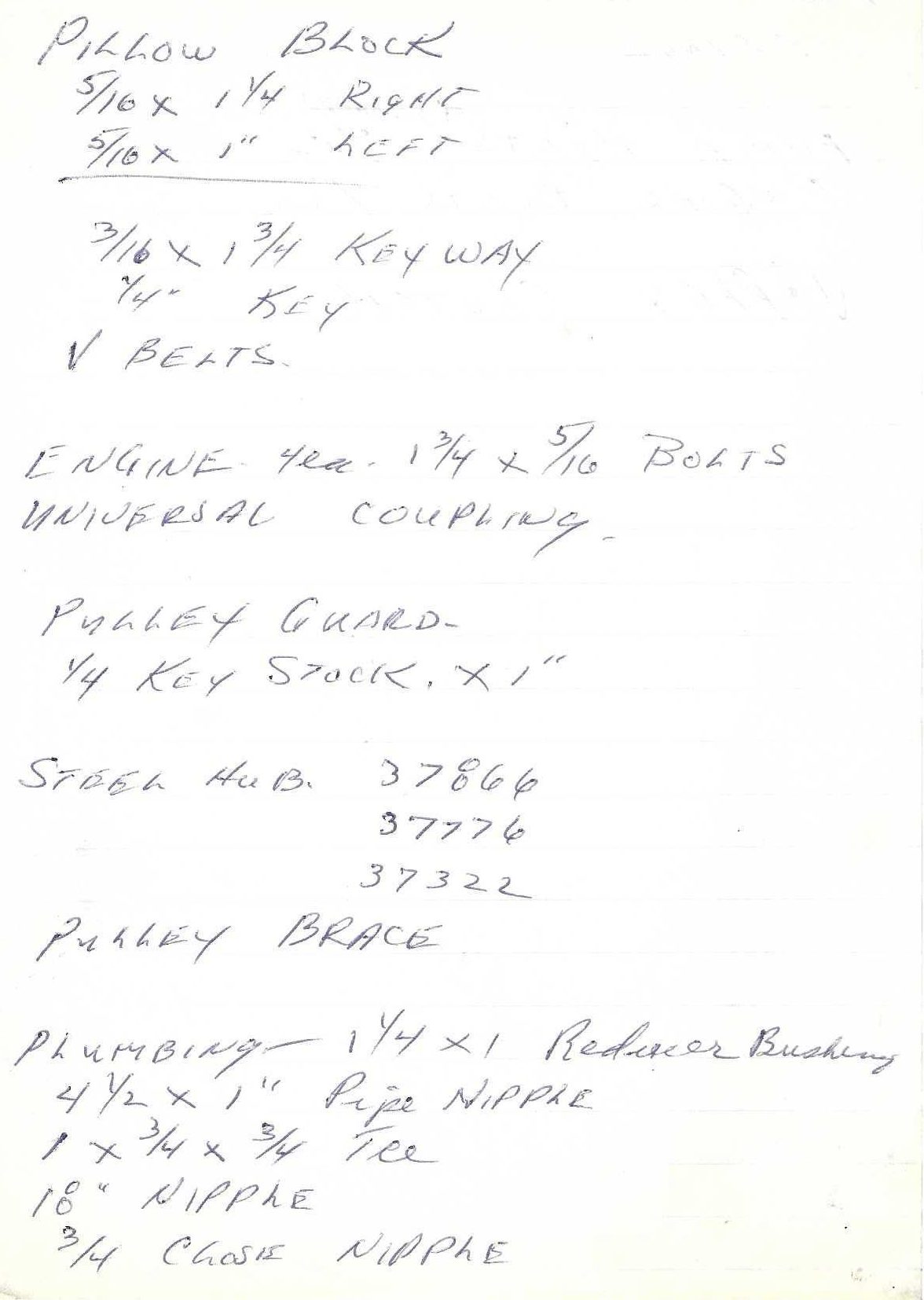
Handwritten note (blue ink, block capitals with some cursive) on plain paper — a parts/hardware list.
PILLOW BLOCK
 5/16 x 1 1/4  RIGHT
 5/16 x 1"     LEFT
------------------------------
 3/16 x 1 3/4 KEYWAY
 1/4" KEY
 V BELTS.

ENGINE 4ea. 1 3/4 x 5/16 BOLTS
UNIVERSAL COUPLING.

PULLEY GUARD-
 1/4 KEY STOCK, x 1"

STEEL HUB.  37866
            37776
            37322
PULLEY BRACE

PLUMBING— 1 1/4 x 1 Reducer Bushing
 4 1/2 x 1" Pipe NIPPLE
 1 x 3/4 x 3/4 Tee
 18" NIPPLE
 3/4 CLOSE NIPPLE
Notes: pillow-block bolts 5/16 x 1-1/4 (right) and 5/16 x 1 (left); keyway 3/16 x 1-3/4; 1/4" key; engine mounted with 4 bolts 1-3/4 x 5/16; universal coupling; steel hub part numbers 37866, 37776, 37322 (supplier not stated); plumbing list includes 1-1/4 x 1 reducer bushing, 4-1/2 x 1" pipe nipple, 1 x 3/4 x 3/4 tee, 18" nipple, 3/4 close nipple. Second digit of "37866" could be read "37ʼ866" (a small mark over the 8); recorded as 37866.
Page 2 of 50
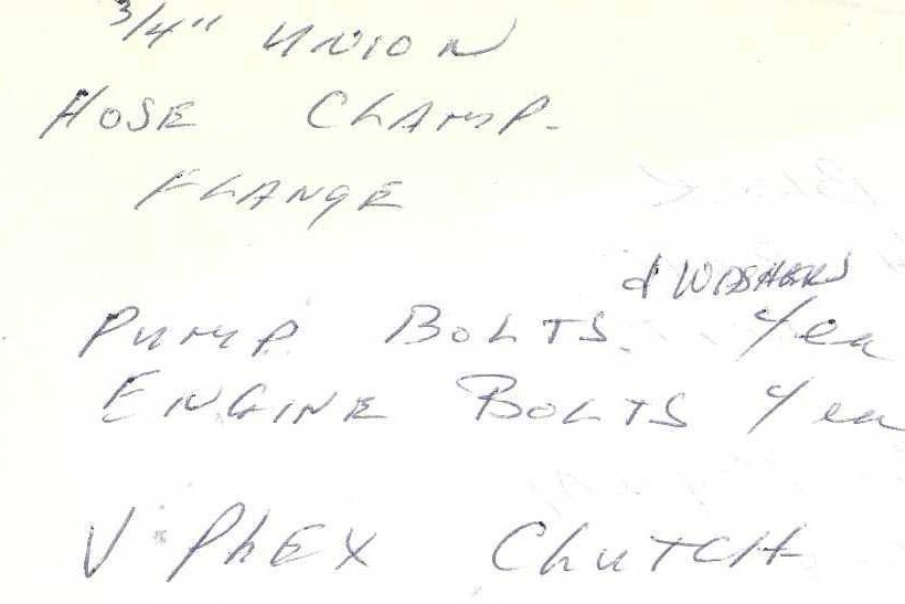
Handwritten note (blue ink), continuation of page 1 list (reverse side; page 1 bleeds through faintly).
3/4" UNION
HOSE CLAMP.
 FLANGE

PUMP BOLTS  [& WASHERS — inserted above]  4ea
ENGINE BOLTS 4ea

V-PLEX CLUTCH
Notes: pump mounted with 4 bolts (and washers); engine 4 bolts; "V-PLEX" clutch (reading "V·PLEX"; possibly a brand name of a V-belt clutch).
Page 3 of 50
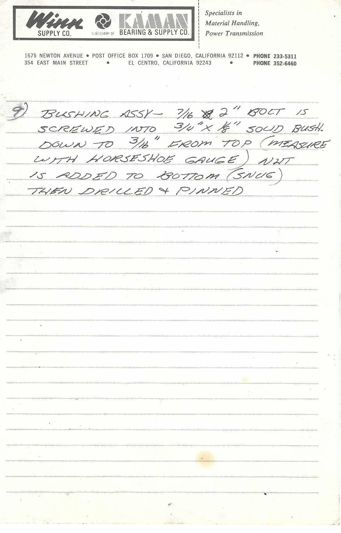
Handwritten assembly step (block capitals, blue ink) on printed letterhead notepad.
Letterhead: Winn Supply Co., "Subsidiary of KAMAN Bearing & Supply Co." — "Specialists in Material Handling, Power Transmission". 1675 Newton Avenue • Post Office Box 1709 • San Diego, California 92112 • Phone 233-5311; 354 East Main Street • El Centro, California 92243 • Phone 352-6460.
9) BUSHING ASSY— 7/16 ~~x~~ 2" BOLT IS
SCREWED INTO 3/4" x 1/8" SOLID BUSH.
DOWN TO 3/16" FROM TOP (MEASURE
WITH HORSESHOE GAUGE) NUT
IS ADDED TO BOTTOM (SNUG)
THEN DRILLED & PINNED
Notes: This is step 9 of the Pressure Adjusting Valve procedure on page 4. 7/16 x 2" bolt threaded into 3/4" x 1/8" solid bushing to a depth leaving 3/16" from top (checked with a horseshoe gauge), nut snugged on the bottom, then drilled and pinned. ("3/4 x 1/8" is presumably a pipe-thread reducing bushing designation, as written.)
Page 4 of 50
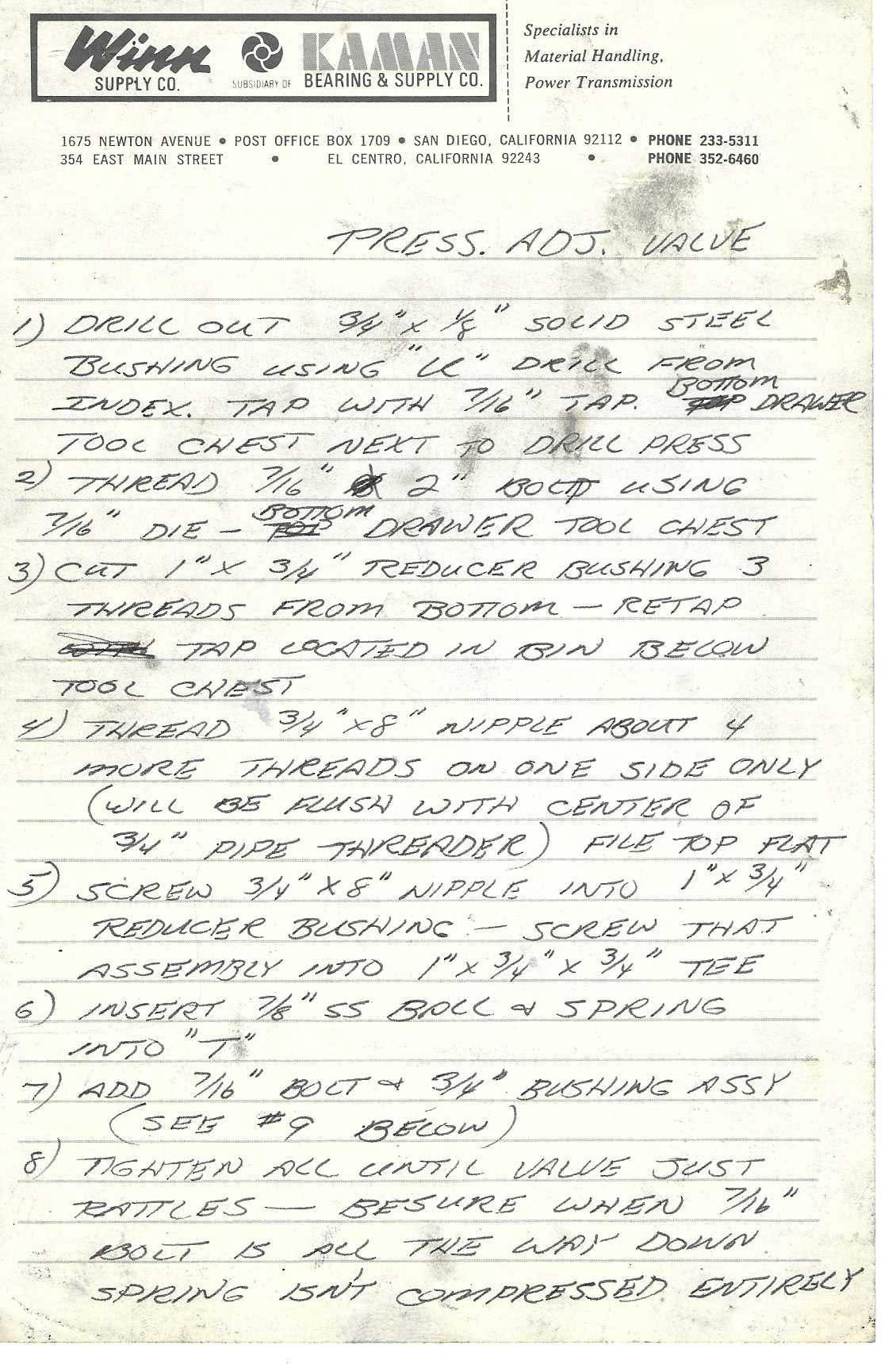
Handwritten assembly procedure (block capitals, black/blue ink) on Winn Supply Co. / Kaman letterhead (same as page 3). Title: PRESS. ADJ. VALVE (pressure adjusting valve).
PRESS. ADJ. VALVE

1) DRILL OUT 3/4" x 1/8" SOLID STEEL
   BUSHING USING "U" DRILL FROM
   INDEX. TAP WITH 7/16" TAP. [Bottom — inserted; "Top" struck] DRAWER
   TOOL CHEST NEXT TO DRILL PRESS
2) THREAD 7/16" ~~x~~ 2" BOLT USING
   7/16" DIE — [BOTTOM inserted; "TOP" struck] DRAWER TOOL CHEST
3) CUT 1" x 3/4" REDUCER BUSHING 3
   THREADS FROM BOTTOM — RETAP
   ~~[struck word]~~ TAP LOCATED IN BIN BELOW
   TOOL CHEST
4) THREAD 3/4" x 8" NIPPLE ABOUT 4
   MORE THREADS ON ONE SIDE ONLY
   (WILL BE FLUSH WITH CENTER OF
   3/4" PIPE THREADER) FILE TOP FLAT
5) SCREW 3/4" x 8" NIPPLE INTO 1" x 3/4"
   REDUCER BUSHING — SCREW THAT
   ASSEMBLY INTO 1" x 3/4" x 3/4" TEE
6) INSERT 7/8" SS BALL & SPRING
   INTO "T"
7) ADD 7/16" BOLT & 3/4" BUSHING ASSY
   (SEE #9 BELOW)
8) TIGHTEN ALL UNTIL VALVE JUST
   RATTLES — BESURE WHEN 7/16"
   BOLT IS ALL THE WAY DOWN
   SPRING ISN'T COMPRESSED ENTIRELY
Notes / geometry: The pressure adjusting (relief/bypass) valve is a spring-loaded ball check built in a 1" x 3/4" x 3/4" pipe tee: a 3/4" x 8" nipple (filed flat on top, the seat) screwed into a 1" x 3/4" reducer bushing (shortened to 3 threads) in the tee; a 7/8" stainless-steel ball and spring sit in the tee; a 7/16" x 2" bolt (adjuster screw) threads through a drilled ("U" letter drill) and 7/16"-tapped 3/4" x 1/8" solid steel bushing to compress the spring. Step 9 is on page 3. Shop references: drill index, tool chest next to drill press, bin below tool chest.
Page 5 of 50
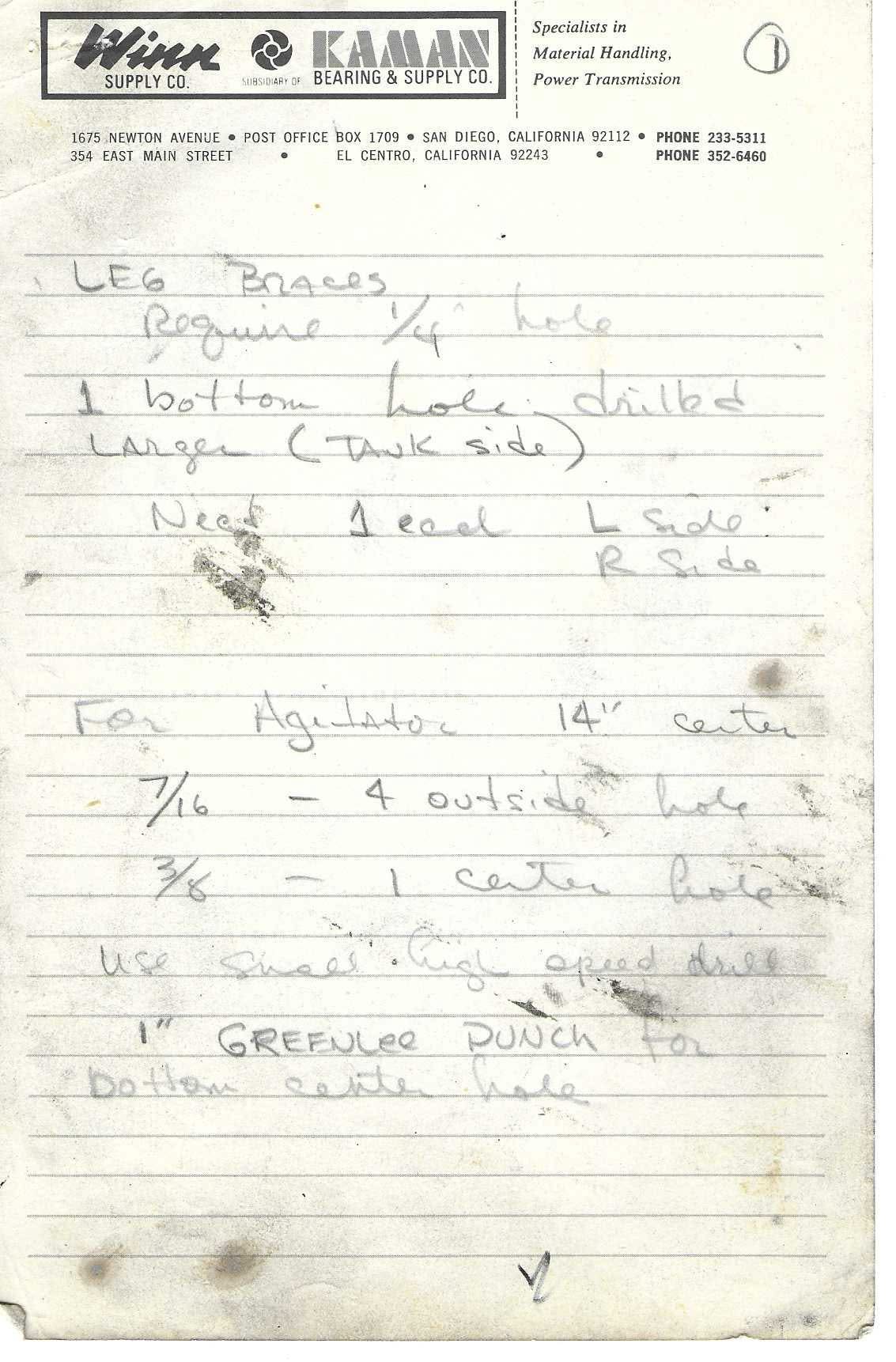
Handwritten note (pencil, cursive mixed with print) on Winn Supply Co. / Kaman letterhead; circled "1" at top right; check mark at bottom.
LEG Braces
  Require 1/4" hole
1 bottom hole drilled
LARGER (TANK side)
   Need 1 each  L side
                R side

For Agitator 14" center
  7/16 — 4 outside hole
  3/8  — 1 center hole
use small high speed drill
  1" GREENLEE PUNCH for
bottom center hole
Notes: leg braces need a 1/4" hole; one bottom hole drilled larger on the tank side; one left and one right brace. Agitator: "14" center" (hole pattern/centers 14" — exact meaning as written), four 7/16" outside holes and one 3/8" center hole; 1" Greenlee punch for bottom center hole.
Page 6 of 50
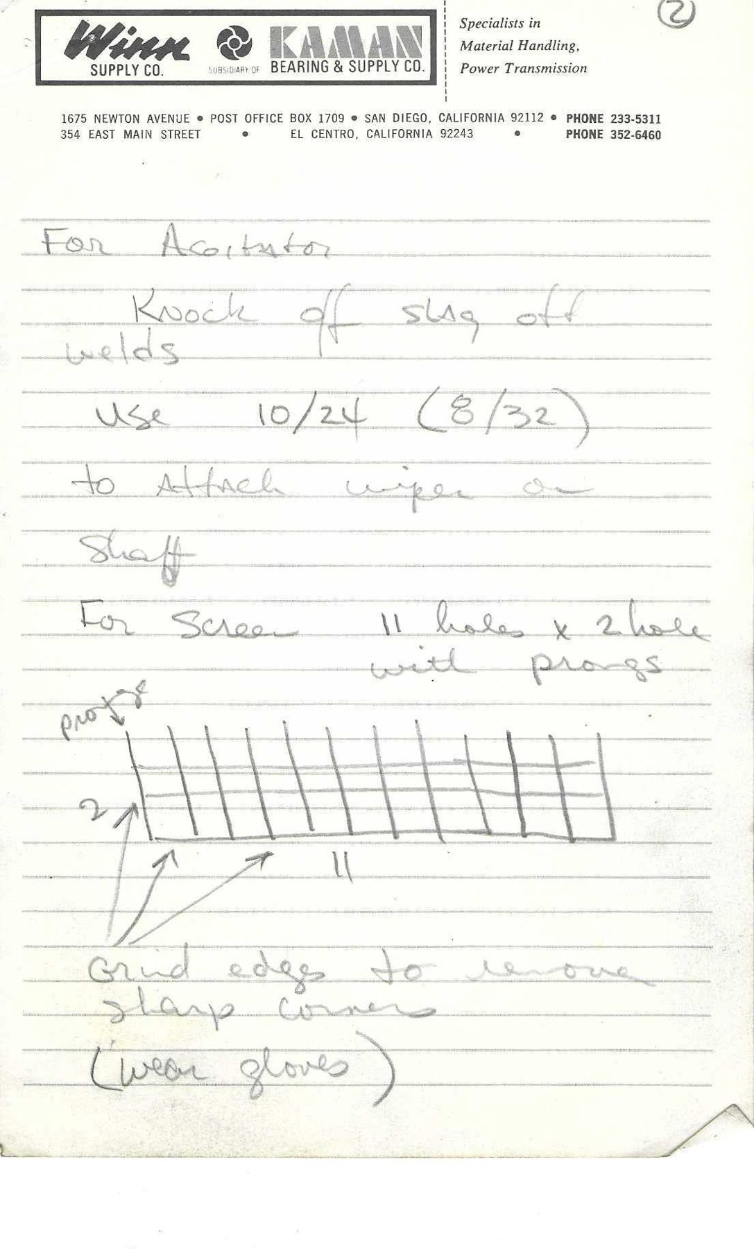
Handwritten note (pencil, cursive) on Winn Supply Co. / Kaman letterhead; circled "2" at top right (continuation of page 5). Includes a small sketch.
For Agitator
  Knock off slag off
welds
  Use 10/24 (8/32)
to Attach wiper on
Shaft
For Screen  11 holes x 2 hole
            with prongs
[sketch]
Grind edges to remove
sharp corners
(wear gloves)
Sketch: a rectangular grid/screen drawn as a row of 11 vertical bars (labeled "11" below) crossed by 2 horizontal bars (labeled "2" at left), with "prongs" (label at upper left, arrow pointing to the protruding top ends of the vertical bars). Arrows from the lower-left point to the bottom edge, tied to the note "Grind edges to remove sharp corners". No dimensions given. Interpreted as a cut piece of grating/expanded screen 11 openings by 2 openings, with prongs left protruding.
Agitator wiper attaches to shaft with 10-24 screw (alternative 8-32).
Page 7 of 50
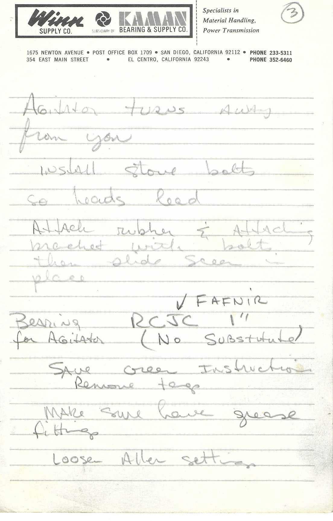
Handwritten note (pencil, cursive) on Winn Supply Co. / Kaman letterhead; circled "3" (continuation of agitator notes, pages 5–6).
Agitator turns Away
from you
  install stove bolts
so heads lead
Attach rubber & Attaching
bracket with bolt,
then slide Screen in
place
                 ✓ FAFNIR
Bearing          RCJC  1"
for Agitator  (NO SUBSTITUTE)
  Save green Instructions
   Remove tags
  MAKE sure have grease
fittings
  Loosen Allen setting[s?]
Notes: agitator rotation direction "turns away from you"; stove bolts installed so heads lead (in direction of rotation); rubber [wiper] and attaching bracket bolted on, then screen slid into place. Agitator bearing: Fafnir RCJC 1" (flange-mount ball bearing unit, 1" bore) — "NO SUBSTITUTE". Bearing must have grease fittings; loosen Allen set screws [last word partly uncertain: "setting[s?]"].
Page 8 of 50
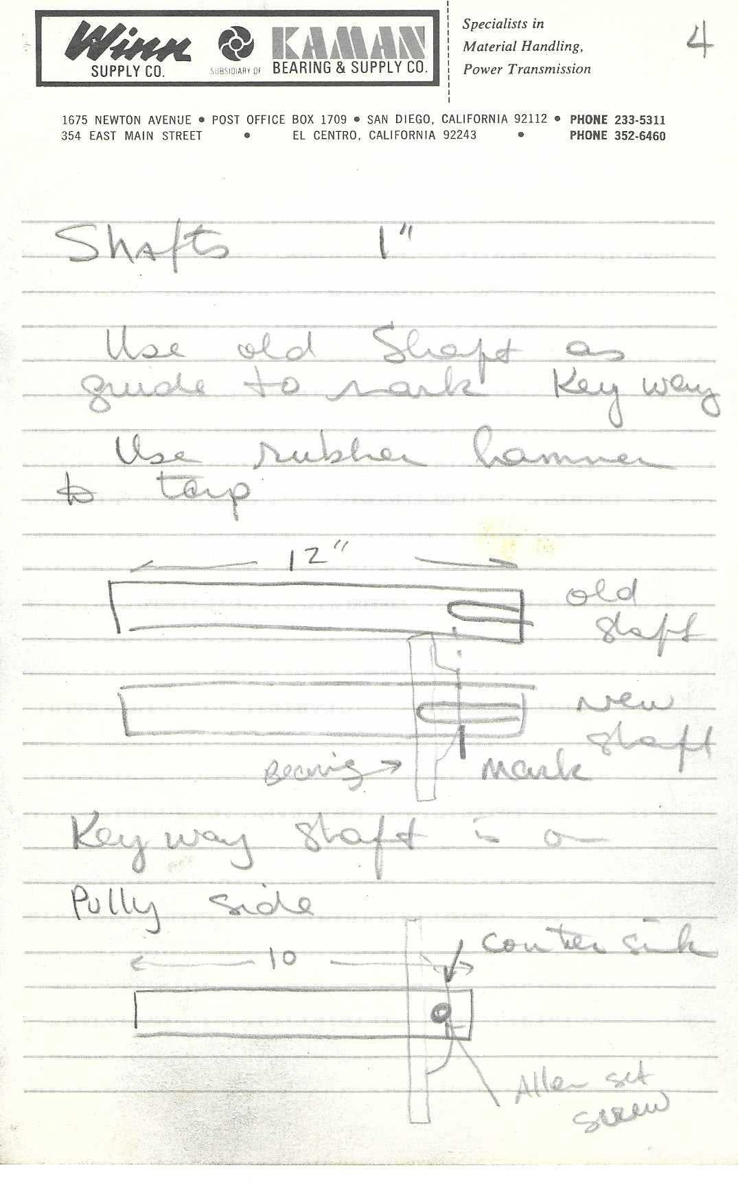
Handwritten note with two sketches (pencil) on Winn Supply Co. / Kaman letterhead; "4" at top right.
Shafts   1"

Use old Shaft as
guide to mark Key way
Use rubber hammer
to tap
[sketch 1]
Key way Shaft is on
Pully side
[sketch 2]
Sketch 1: two horizontal shafts drawn one above the other. Upper labeled "old shaft", lower "new shaft"; dimension arrow over the upper shaft "12"" (shaft length 12"). Both have a keyway slot drawn at the right end. A vertical member labeled "bearing →" crosses near the right end; a vertical tick on the new shaft labeled "mark" — i.e., the bearing position/keyway is transferred from the old shaft to the new.
Sketch 2: a single shaft with dimension arrow "10" (10", unit not written) running to a vertical plate/bearing at the right; a small circle near the right end labeled "Allen set screw", with an arrow labeled "counter sink" pointing to the set-screw location (countersink/spot in shaft for the set screw).
Notes: shafts are 1" diameter; one shaft 12" long (keyway end at pulley side), another 10" with a countersink for an Allen set screw.
Page 9 of 50
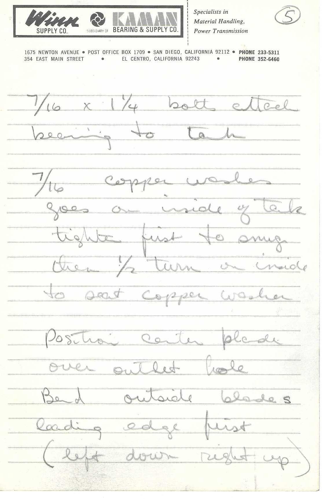
Handwritten note (pencil, cursive) on Winn Supply Co. / Kaman letterhead; circled "5".
7/16 x 1 1/4 bolt attach
bearing to tank

7/16 copper washer
goes on inside of tank
tighten first to snug,
then 1/2 turn on inside
to seat copper washer

Position center blade
over outlet hole
Bend outside blades
leading edge first
(left down right up)
Notes: agitator bearing bolts to tank with 7/16 x 1-1/4 bolts; 7/16 copper sealing washers inside tank; snug then 1/2 turn. Agitator has a center blade positioned over the tank outlet hole, and outside blades bent at the leading edge (left down, right up) — i.e., pitched paddles.
Page 10 of 50
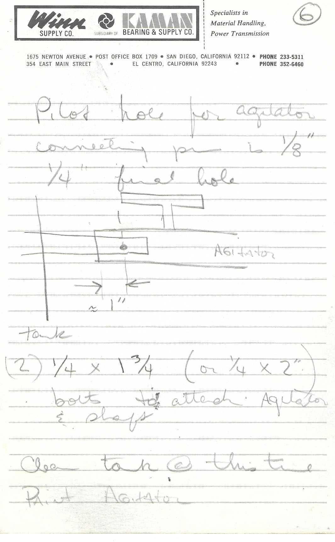
Handwritten note with sketch (pencil) on Winn Supply Co. / Kaman letterhead; circled "6".
Pilot hole for agitator
connecting pin is 1/8"
1/4" final hole
[sketch]
(2) 1/4 x 1 3/4  (or 1/4 x 2")
  bolts to attach Agitator
  & shaft
Clean tank @ this time
Paint Agitator
Sketch: a vertical line at left labeled "tank" (tank wall). A horizontal shaft enters from the wall into a rectangular hub/collar labeled "Agitator" with a dot (the cross pin / pin hole) in it. Above, a T-shaped member (a blade or bracket on a stem) is drawn over the hub. Dimension arrows below give the distance from the tank wall to the pin hole as "≈ 1"" (approximately 1").
Notes: agitator connecting pin: 1/8" pilot hole, 1/4" final hole, roughly 1" in from the tank wall; two 1/4 x 1-3/4 (or 1/4 x 2") bolts attach agitator to shaft.
Page 11 of 50
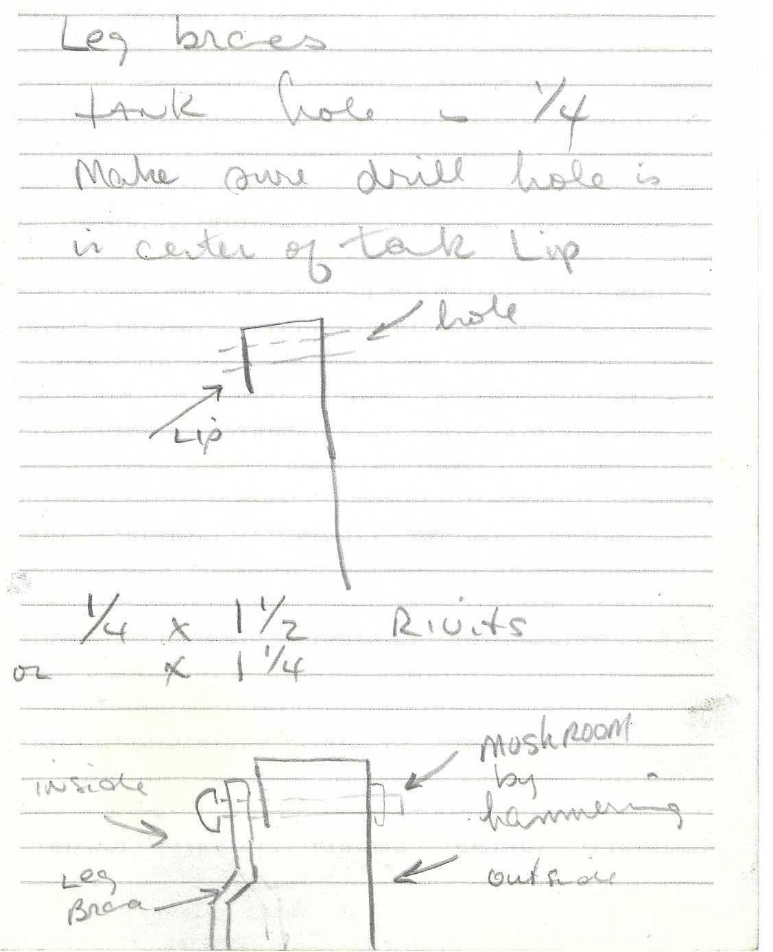
Handwritten note with two sketches (pencil) on Winn Supply Co. / Kaman letterhead; circled "7".
Leg braces
 tank hole — 1/4
 Make sure drill hole is
 in center of tank Lip
[sketch 1]
 1/4 x 1 1/2  Rivets
or    x 1 1/4
[sketch 2]
Sketch 1: profile of the tank's top edge — a vertical wall with an outward-turned rim; arrow "Lip" points to the rolled/flanged lip, arrow "hole" points to a horizontal drilled hole through the lip region (dashed lines showing hole through lip).
Sketch 2: section of the rivet joint: a rivet passes through the tank lip and a "Leg Brace" (arrow to a bent bar on the inside face, shown jogged/offset). Labels: "inside" (arrow pointing to the rivet head side, round head inside), "outside" (arrow to the outer face), and "MUSHROOM by hammering" (arrow to the rivet tail on the outside, peened over).
Notes: leg braces riveted to tank lip through 1/4" holes centered in the lip, using 1/4 x 1-1/2 (or 1/4 x 1-1/4) rivets, head inside, tail mushroomed outside by hammering. (Note: the arrows in sketch 2 put "inside" on the left/brace side and "outside" on the right; the leg brace is on the inside face of the wall.)
Page 12 of 50
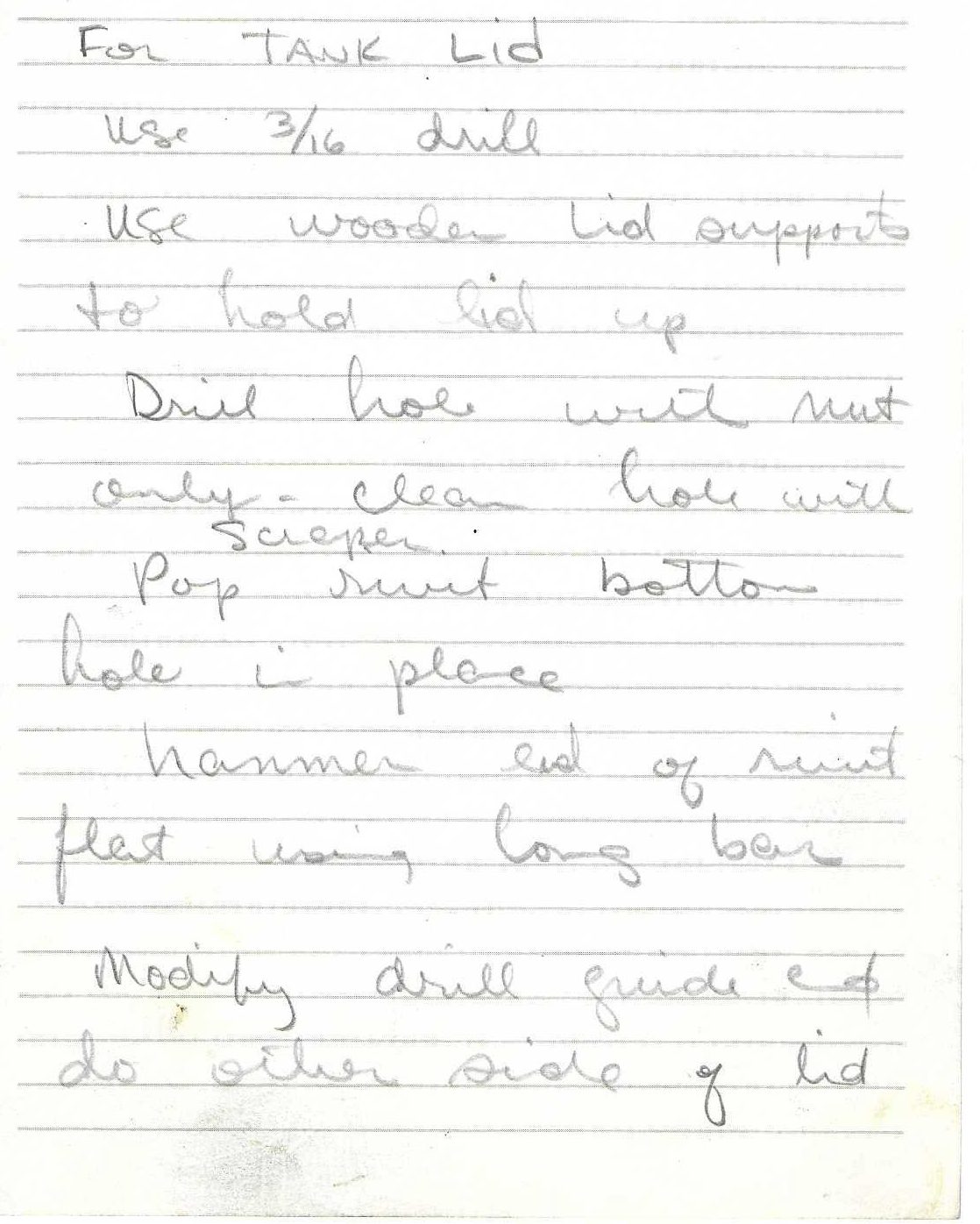
Handwritten note (pencil, cursive) on Winn Supply Co. / Kaman letterhead; circled "8".
For TANK LID
 Use 3/16 drill
 Use wooden lid supports
to hold lid up
 Drill hole with [rivet?] [riveting?]
only - clean hole with
 Scraper
 Pop rivet bottom
hole in place
 hammer end of rivet
flat using long bar
 Modify drill guide & [and?]
do other side of lid
Notes: tank lid (hinged lid presumably) attached with pop rivets in 3/16" holes; wooden supports hold lid up during drilling; rivet tails hammered flat with a long bar; a drill guide is used for both sides of lid. The word after "Drill hole with" is unclear (looks like "rivet"/"rivit" — possibly "Drill hole with [lid] [nut?] only").
Page 13 of 50
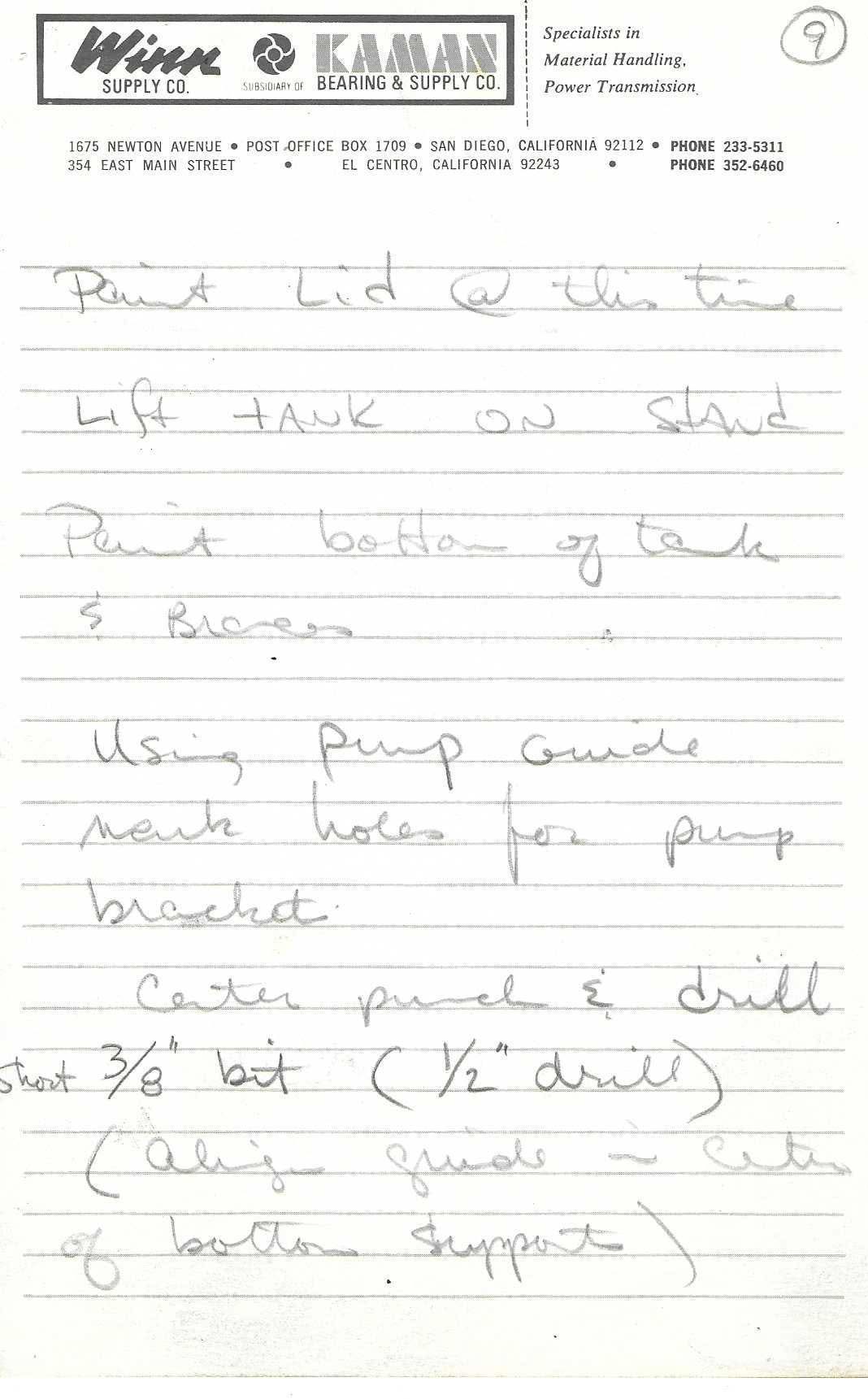
Handwritten note (pencil, cursive) on Winn Supply Co. / Kaman letterhead; circled "9".
Paint Lid @ this time
Lift TANK ON Stand
Paint bottom of tank
& Braces

Using pump Guide
mark holes for pump
bracket
  Center punch & drill
short 3/8" bit (1/2" drill)
 (align guide — center
 of bottom support)
Notes: tank is lifted onto a stand; pump bracket holes located with a "pump guide" jig aligned to the center of the bottom support; drilled with a short 3/8" bit in a 1/2" drill (motor).
Page 14 of 50
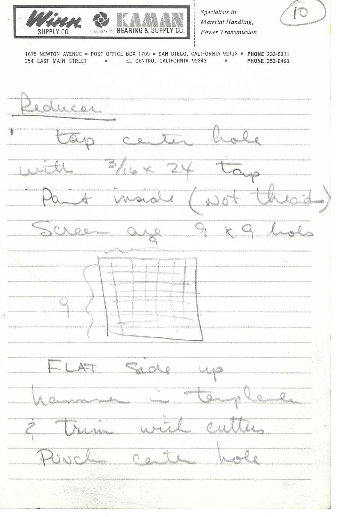
Handwritten note with sketch (pencil) on Winn Supply Co. / Kaman letterhead; circled "10".
Reducer  [underlined]
 tap center hole
with 3/16 x 24 tap
 Paint inside (Not thread)
Screen are 9 x 9 holes
[sketch]
 FLAT side up
hammer in template
& trim with cutters.
 Punch center hole
Sketch: a square grid labeled "9" across the top (brace) and "9" on the left side (brace) — a screen of 9 x 9 openings. No dimensions.
Notes: "Reducer" center hole tapped 3/16 x 24 (as written; a 3/16-24 thread is unusual — recorded verbatim). Second screen (distinct from the 11 x 2 agitator screen on page 6) is 9 x 9 holes, hammered flat-side-up into a template, trimmed with cutters, center hole punched.
Page 15 of 50
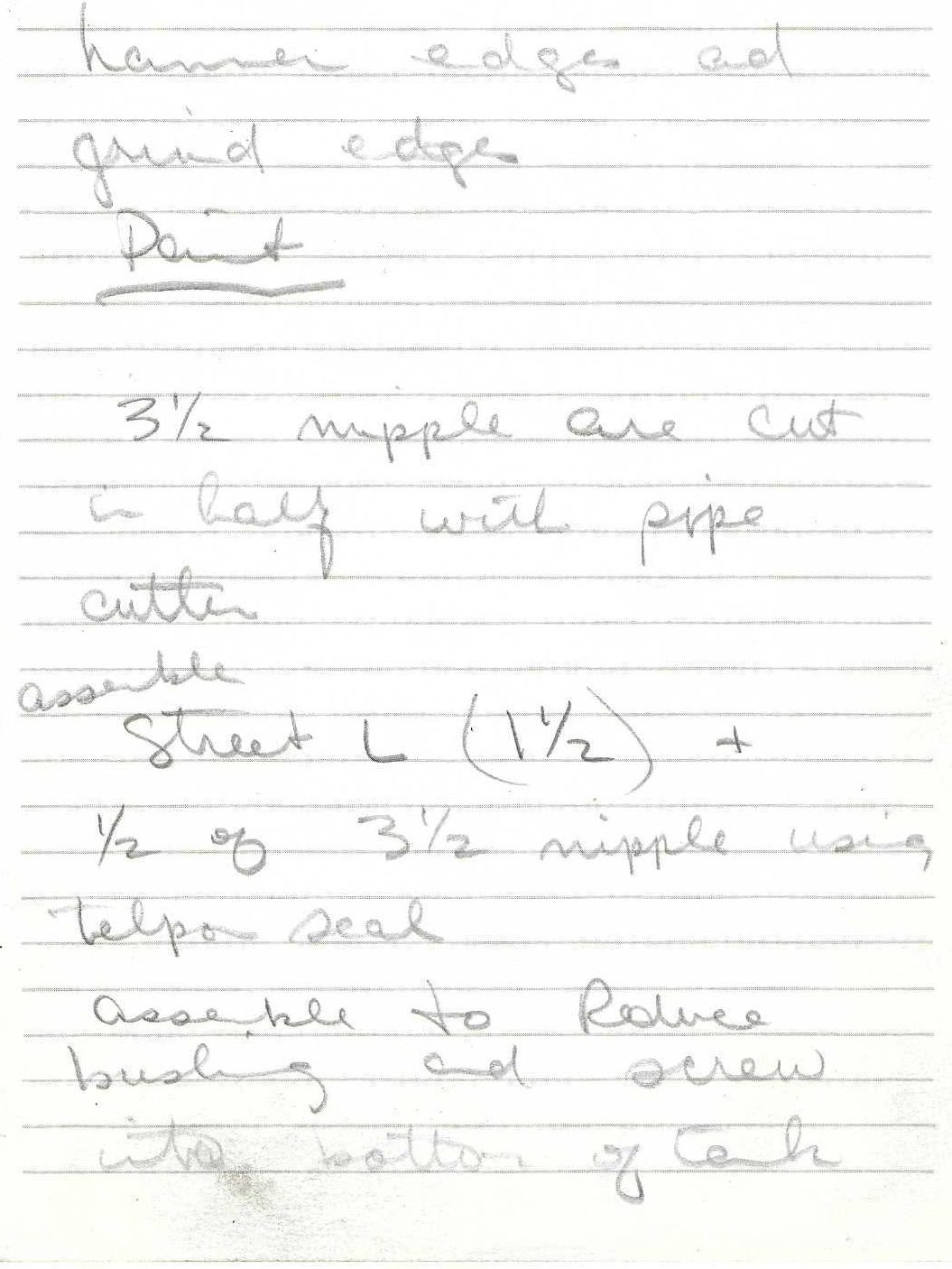
Handwritten note (pencil, cursive) on Winn Supply Co. / Kaman letterhead; circled "11" (continuation of page 14).
hammer edges and
grind edges
Paint  [underlined]

 3 1/2 nipple are cut
in half with pipe
cutter
assemble
 Street L (1 1/2) +
1/2 of 3 1/2 nipple using
Teflon seal
assemble to Reduce[r]
bushing and screw
into bottom of tank
Notes: tank bottom outlet: a 1-1/2" street elbow plus half of a 3-1/2" nipple (nipples cut in half with pipe cutter), sealed with Teflon, assembled to the reducer bushing and screwed into the bottom of the tank. ("1 1/2" in parentheses likely the street-L pipe size.)
Page 16 of 50
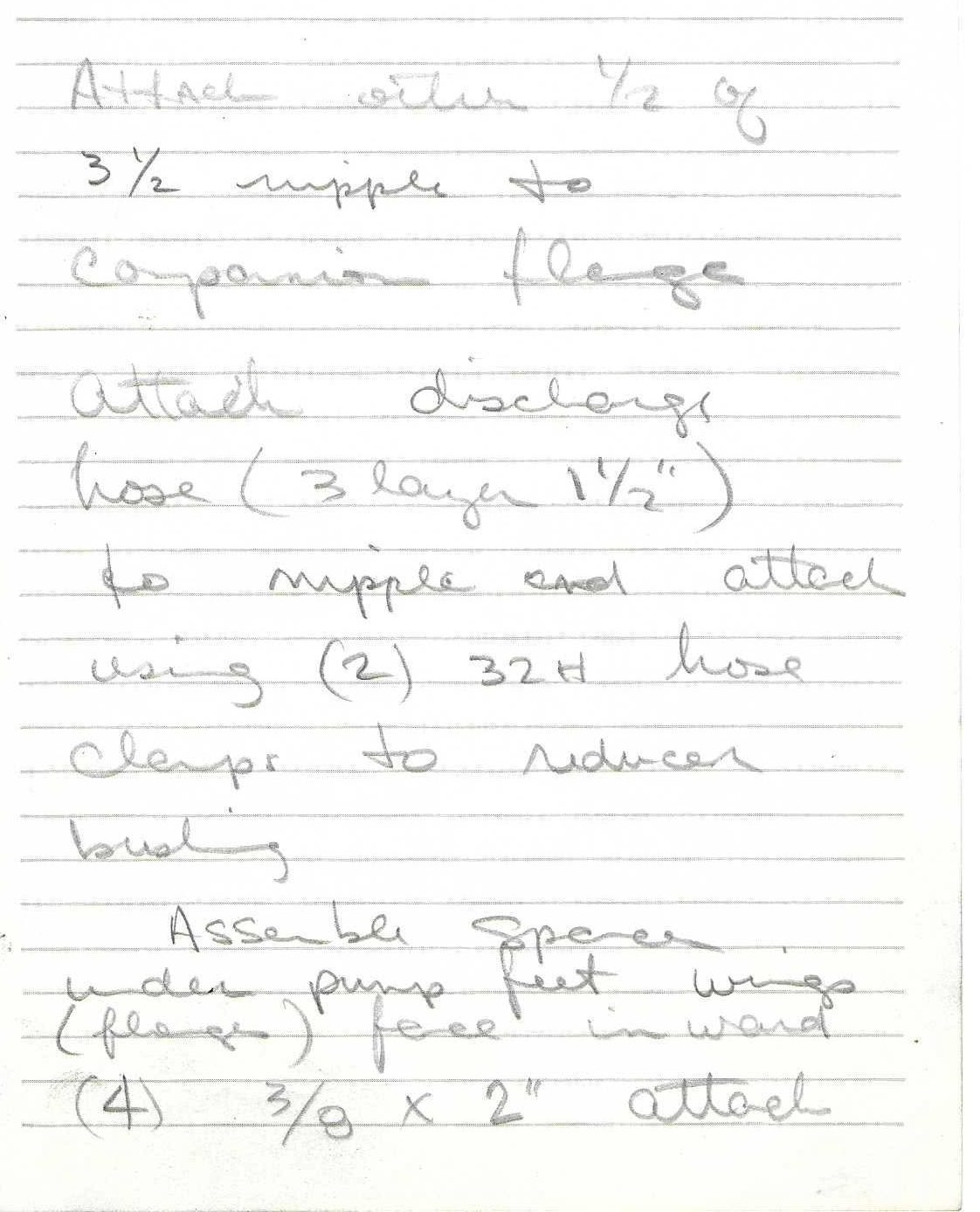
Handwritten note (pencil, cursive) on Winn Supply Co. / Kaman letterhead; circled "12".
Attach other 1/2 of
3 1/2 nipple to
Companion flange
attach discharge
hose (3 layer 1 1/2")
to nipple and attach
using (2) 32H hose
clamps to reducer
bushing
  Assemble Spacer
under pump feet wings
(flange) face inward
(4) 3/8 x 2" attach
Notes: the other half of the cut 3-1/2" nipple goes into a companion flange (which bolts to the pump inlet, page 17). A 1-1/2" three-ply hose connects the tank outlet nipple to the reducer bushing with two size "32H" hose clamps. (The note calls it "discharge hose", though from context it runs tank→pump.) Spacers go under the pump feet "wings" with flange facing inward; four 3/8 x 2" bolts (continued on page 17).
Page 17 of 50
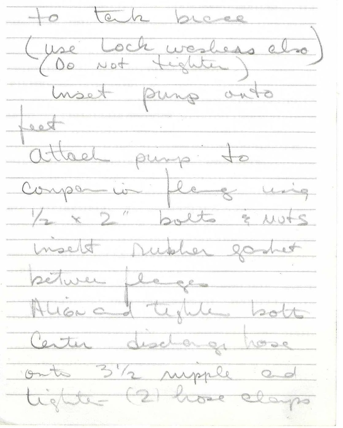
Handwritten note (pencil, cursive) on Winn Supply Co. / Kaman letterhead; no page number visible (continuation of page 16, likely "13").
to tank brace
(use Lock washers also)
(Do NOT tighten)
  Insert pump onto
feet
 attach pump to
Companion flange using
1/2 x 2" bolts & NUTS
 insert rubber gasket
between flanges
 Align and tighten bolt
 Center discharge hose
onto 3 1/2 nipple and
tighten (2) hose clamps
Notes: pump feet/spacers fastened to tank brace with four 3/8 x 2" bolts plus lock washers (left loose until aligned); pump bolted to the companion flange with 1/2 x 2" bolts and nuts, rubber gasket between flanges.
Page 18 of 50
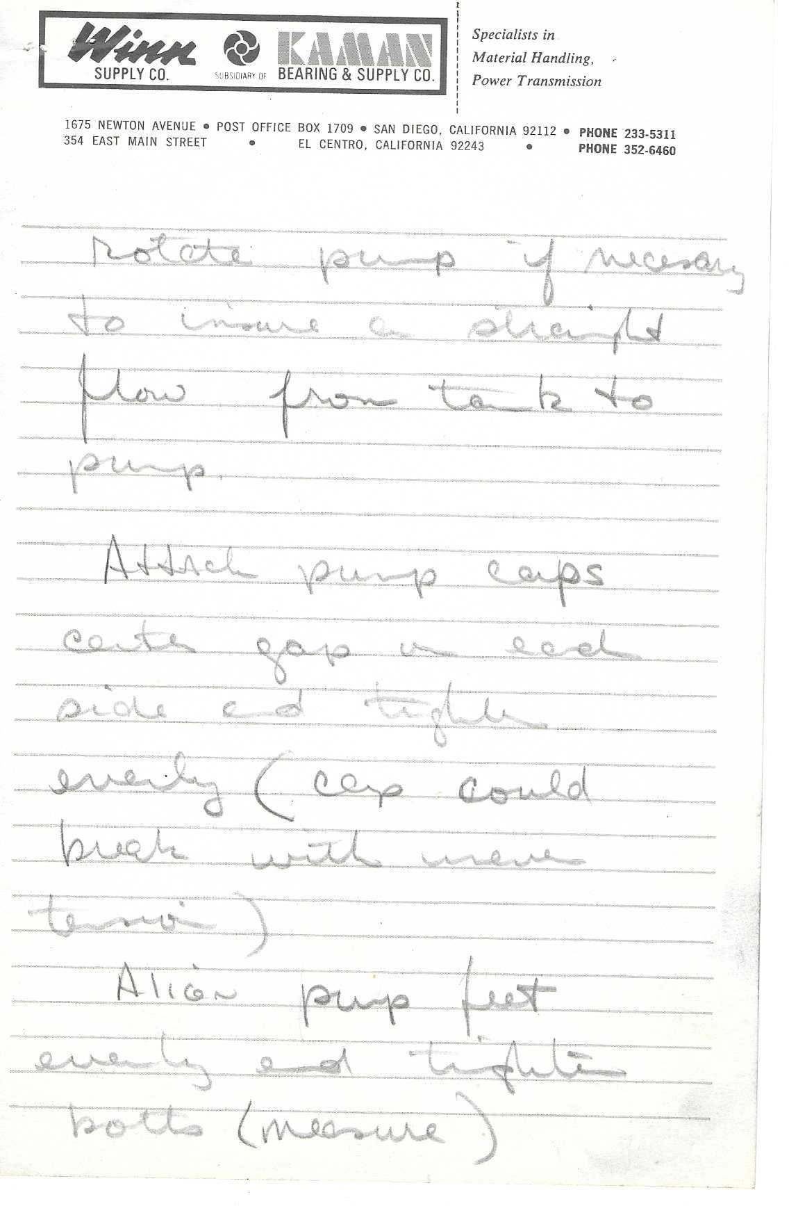
Handwritten note (pencil, cursive, faint) on Winn Supply Co. / Kaman letterhead; no page number visible (continuation, likely "14").
rotate pump if necessary
to insure a straight
flow from tank to
pump.
  Attach pump caps
center gap on each
side and tighten
evenly (cap could
break with more
tension)
  Align pump feet
evenly and tighten
bolts (measure)
Notes: the pump is clocked so the line from tank to pump is straight; pump "caps" (clamps/end caps) are centered with equal gap each side and tightened evenly because over-tension can break the cap.
Page 19 of 50
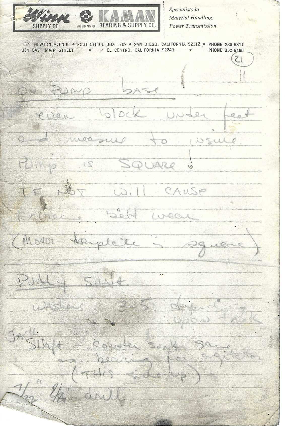
Handwritten note (pencil, mixed print/cursive; smudged, worn) on Winn Supply Co. / Kaman letterhead; circled "21" (the pages numbered 13–20 of this series are not in the PDF at this point).
ON Pump base  [underlined]
  even block under feet
and measure to insure
Pump is SQUARE!
IF NOT will CAUSE
Extreme belt wear
(Motor template is square)
------------------------------
Pully Shaft  [underlined]
  Washers 3-5 depending
          upon tank
JACK
Shaft — counter sink same
   as bearing for agitator
   (THIS side up)
1/32" [7/64?]" drill
Notes: pump must be square to the motor (motor template is square) or belts wear badly. Pulley shaft uses 3–5 washers (shims) depending on tank. Jack shaft is countersunk for set screw the same way as the agitator bearing. The last line is partly torn/smudged: first fraction reads "1/32"" (could be "7/32"", cf. page 20), second fraction illegible-ish "[7/64?]"".
Page 20 of 50
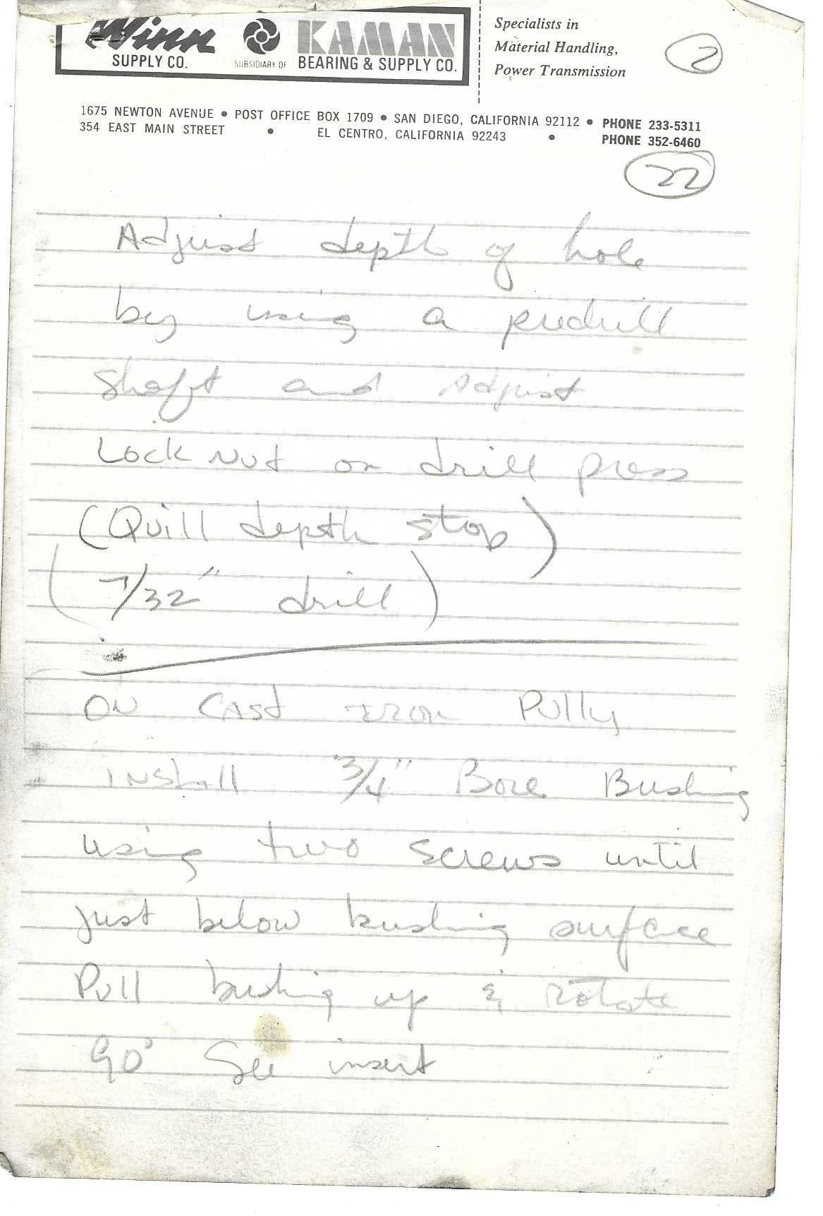
Handwritten note (pencil, cursive) on Winn Supply Co. / Kaman letterhead; circled "2" at top right and circled "22" below letterhead (two numbering series).
Adjust depth of hole
by using a predrill[ed?]
shaft and Adjust
Lock nut on drill press
(Quill depth stop)
(7/32" drill)
------------------------------
ON Cast IRON Pully
 install 3/4" Bore Bushing
using two screws until
just below bushing surface
Pull bushing up & Rotate
90° See insert
Notes: set-screw countersink depth on shafts set with drill-press quill depth stop using a pre-drilled sample shaft; 7/32" drill. Cast-iron pulley takes a 3/4" bore (taper-lock/QD-style) bushing installed with two screws; "See insert" refers to a separate sheet.
Page 21 of 50
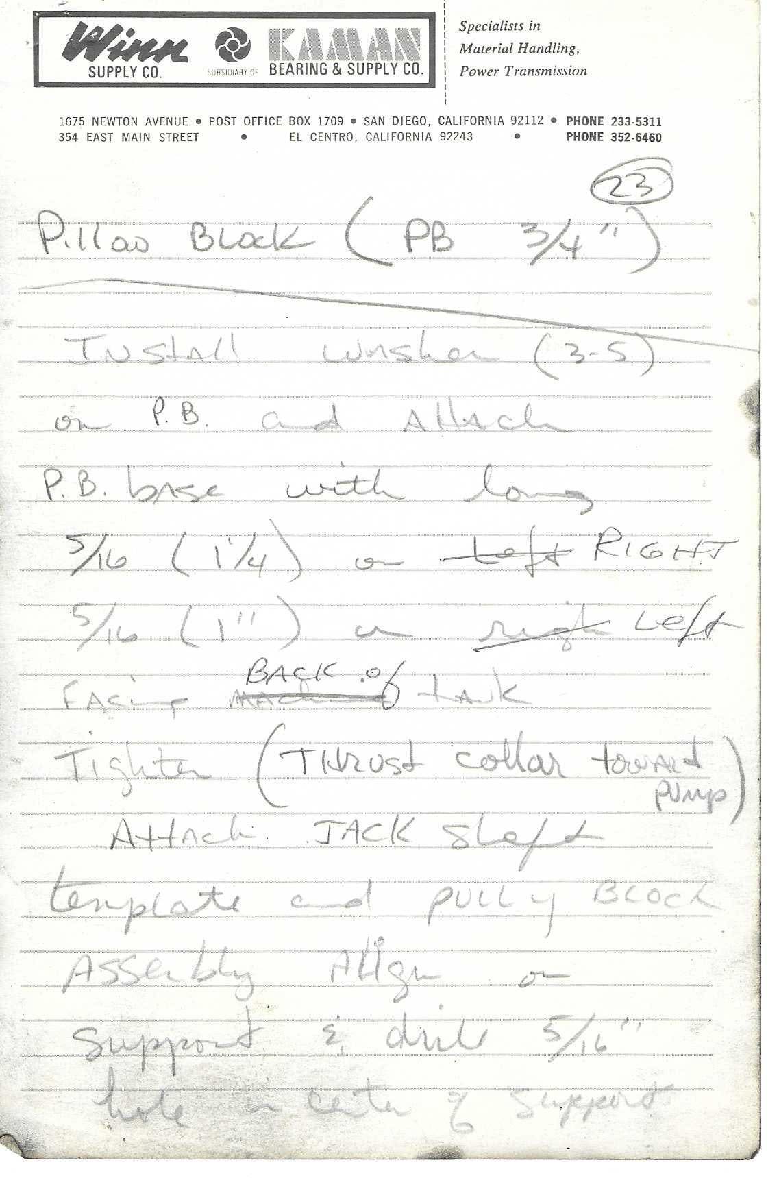
Handwritten note (pencil, mixed print/cursive) on Winn Supply Co. / Kaman letterhead; circled "23".
Pillow Block (PB 3/4")
------------------------------
Install washer (3-5)
on P.B. and Attach
P.B. base with long
5/16 (1 1/4) on ~~Left~~ RIGHT
5/16 (1")    on ~~right~~ Left
Facing ~~[struck word]~~ BACK of tank
Tighten (Thrust collar toward
                          pump)
 Attach JACK shaft
template and pulley BLOCK
Assembly Align on
Support & drill 5/16"
hole in center of support
Notes: jack-shaft pillow blocks are 3/4" bore ("PB 3/4""); 3–5 washers (shims) under pillow block; 5/16 x 1-1/4 bolt on the right, 5/16 x 1" on the left (consistent with page 1), facing back of tank; thrust collar toward the pump. Jack-shaft template and pulley-block assembly aligned on support, 5/16" hole drilled at center of support.
Page 22 of 50
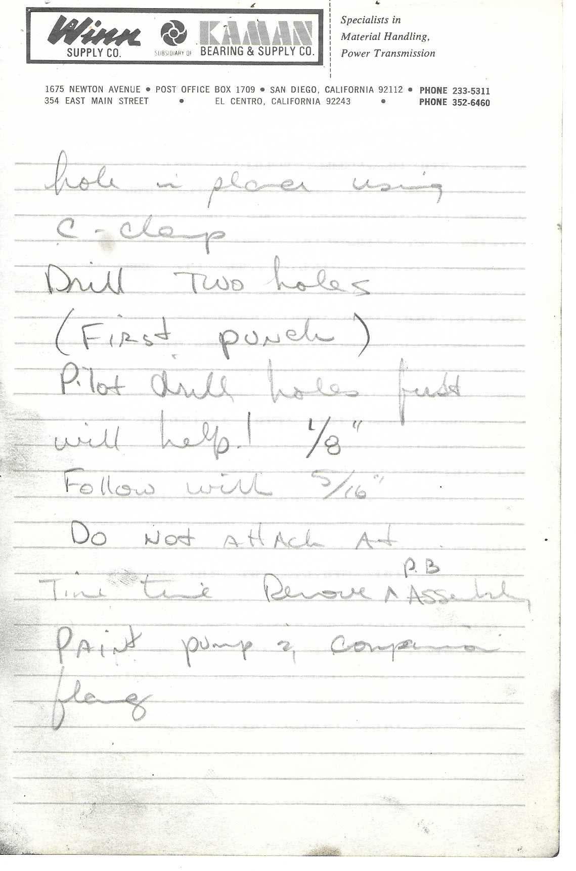
Handwritten note (pencil, cursive/print) on Winn Supply Co. / Kaman letterhead; no page number (continuation of page 21, likely "24").
hole in place using
C-clamp
Drill TWO holes
(First punch)
Pilot drill holes first
will help! 1/8"
Follow with 5/16"
 DO NOT Attach At
This time Remove [P.B — inserted] Assembly
PAINT pump & companion
flange
Notes: jack-shaft pillow-block assembly support holes: center punch, 1/8" pilot, then 5/16"; assembly removed (not attached yet) so pump and companion flange can be painted.
Page 23 of 50
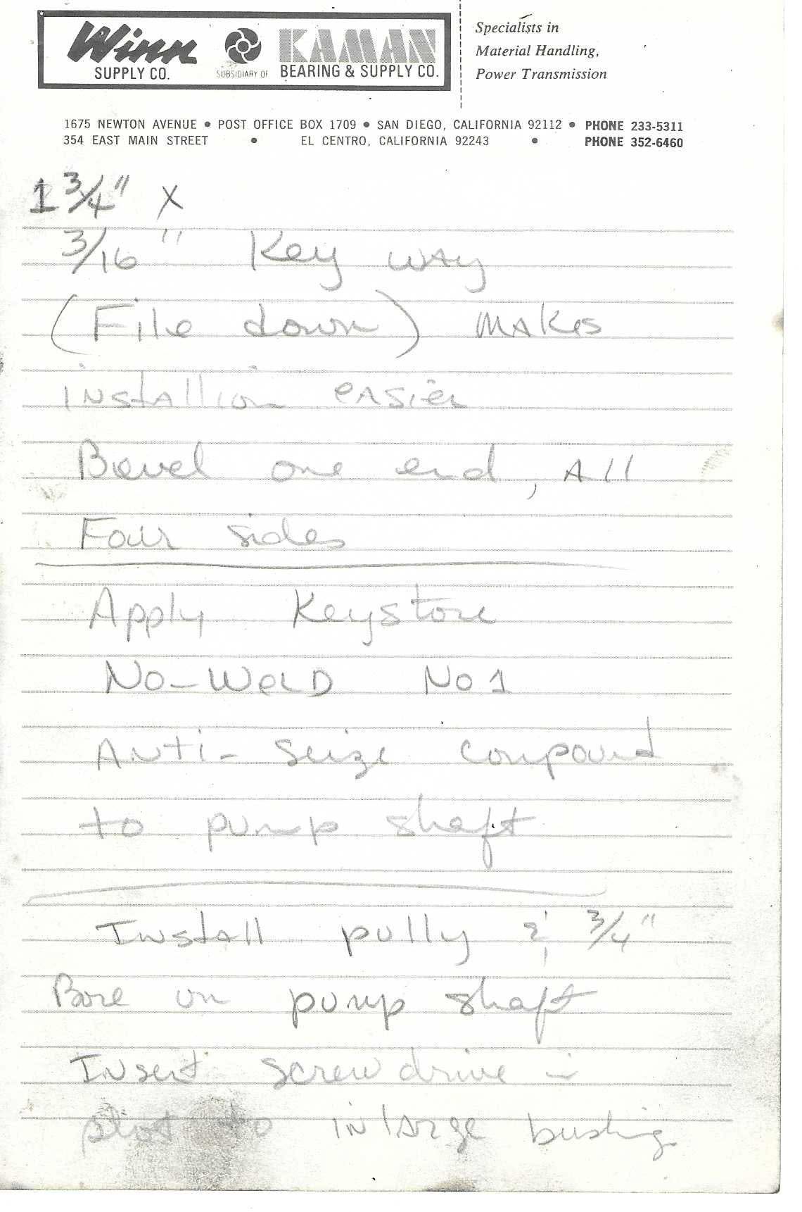
Handwritten note (pencil) on Winn Supply Co. / Kaman letterhead; no page number.
1 3/4" x
3/16" Key way
(File down) makes
installation easier
Bevel one end, All
Four sides
------------------------------
Apply Keystone
NO-WELD No 1
Anti-Seize compound
to pump shaft
------------------------------
Install pully & 3/4"
Bore on pump shaft
Insert screw drive[r] in
slot to [en]large bushing
Notes: key stock 1-3/4" x 3/16" (matches page 1 "3/16 x 1 3/4 keyway"), filed and beveled on one end, all four sides. Keystone "No-Weld No. 1" anti-seize compound on pump shaft. Pulley with 3/4" bore (bushing) on the pump shaft — so the pump shaft is 3/4". Screwdriver in bushing slot to spread it ("slot to [en]large bushing" — first words partly smudged: "[slot to?]").
Page 24 of 50
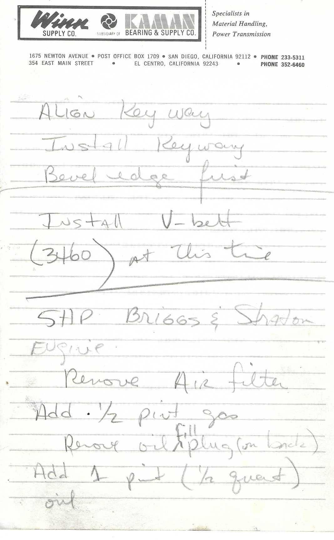
Handwritten note (pencil) on Winn Supply Co. / Kaman letterhead; no page number.
ALIGN Key way
Install Keyway
Bevel edge first
------------------------------
Install V-belt
(3460) at this time   [reading "3460"; could be "3L60" / "3L460"?]
------------------------------
5HP BRIGGS & Stratton
Engine
 Remove Air filter
Add 1/2 pint gas
 Remove oil [fill — inserted] plug (on back)
Add 1 pint (1/2 quart)
oil
Notes: Power unit: 5 HP Briggs & Stratton engine. V-belt part number written "3460" (possibly a 3L-section belt designation; reading uncertain). Initial fill: 1/2 pint gasoline; oil fill plug on back, 1 pint (1/2 quart) oil. (Note: page 1/2 list "ENGINE" bolts and page 19 references a "motor template".)
Page 25 of 50
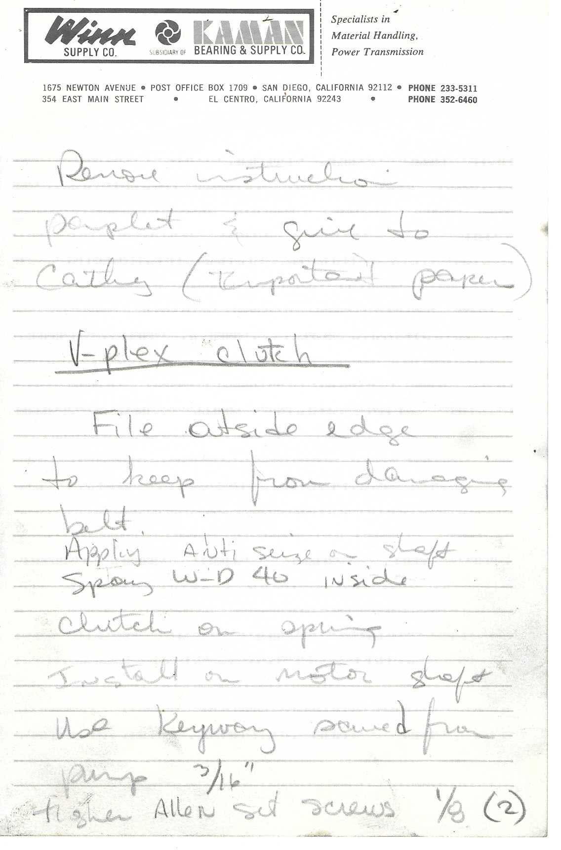
Handwritten note (pencil, cursive) on Winn Supply Co. / Kaman letterhead; no page number.
Remove instruction
pamphlet & give to
Cathy (Important paper)
------------------------------
V-plex clutch  [underlined]
  File outside edge
to keep from damaging
belt.
Apply Anti seize on shaft
Spray W-D 40 inside
clutch on spring
Install on motor shaft
Use Keyway saved from
pump 3/16"
tighten Allen set screws 1/8 (2)
Notes: name "Cathy" — the engine's instruction pamphlet goes to her ("Important paper"). V-Plex clutch (centrifugal, spring inside) mounts on the motor/engine shaft with a 3/16" key saved from the pump; two Allen set screws (1/8" hex key size, as written "1/8 (2)"); outer edge filed so it doesn't damage the belt; WD-40 on clutch spring.
Page 26 of 50
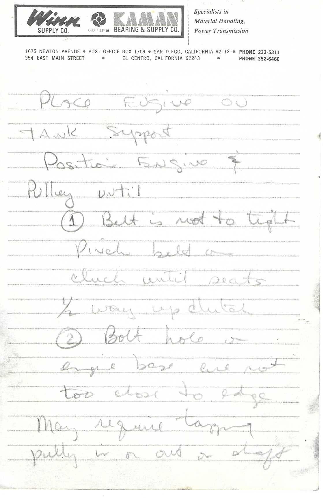
Handwritten note (pencil) on Winn Supply Co. letterhead, ruled. Apparently part of an assembly/installation procedure continuing across pages 26–28.
Printed letterhead: "Winn SUPPLY CO. — subsidiary of KAMAN BEARING & SUPPLY CO. — Specialists in Material Handling, Power Transmission. 1675 Newton Avenue • Post Office Box 1709 • San Diego, California 92112 • Phone 233-5311 / 354 East Main Street • El Centro, California 92243 • Phone 352-6460"
Handwritten:
Place Engine on
Tank Support
Position Engine &
Pulley until
(1) Belt is not to tight
Pinch belt on
cluch until seats
1/2 way up clutch
(2) Bolt hole on
engine base are not
too close to edge
May require tapping
pulley in or out on shaft
Page 27 of 50
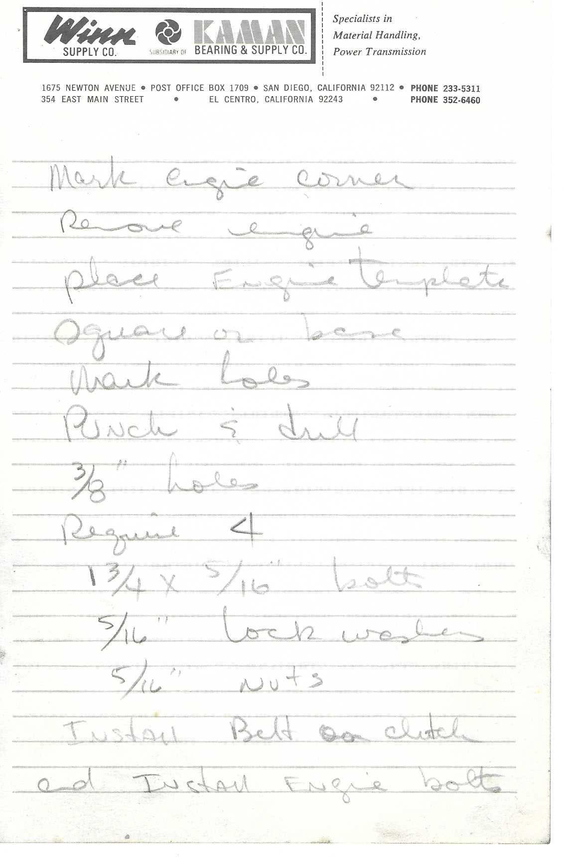
Handwritten note (pencil) on the same Winn Supply Co. letterhead (same printed header as p. 26). Continuation of engine-mounting procedure.
Mark engine corner
Remove engine
place Engine template
square on base
Mark holes
Punch & drill
3/8" holes
Require 4
1 3/4 x 5/16" bolt
5/16" lock washer
5/16" nuts
Install Belt on clutch
and Install Engine bolts
Page 28 of 50
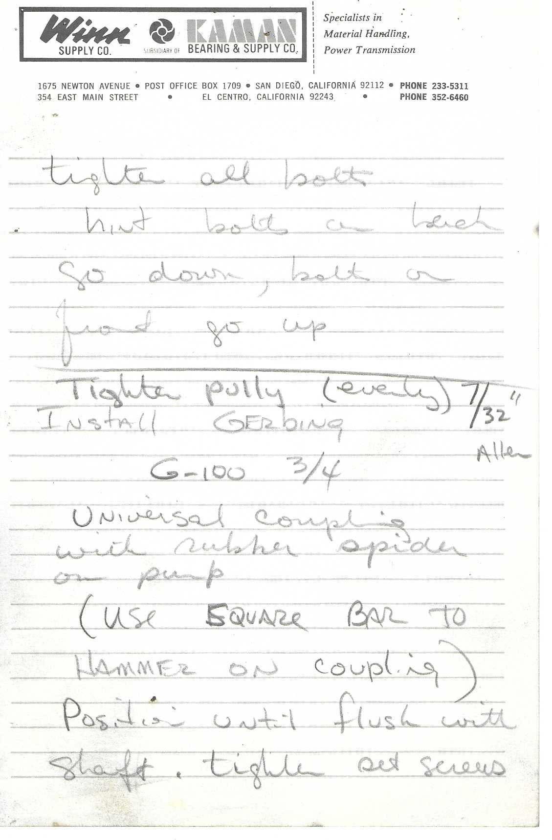
Handwritten note (pencil) on the same Winn Supply Co. letterhead. Continuation: bolting, pulley set screw, pump coupling.
tighten all bolts
[Hint?] bolts on back
go down, bolt on
front go up
———— (horizontal rule drawn across page)
Tighten pully (evenly) 7/32" Allen
Install GERBING
G-100 3/4
Universal coupling
with rubber spider
on pump
(Use SQUARE BAR TO
HAMMER ON coupling)
Position until flush with
shaft. tighten set screws
Notes: "7/32"" and "Allen" written in the right margin beside "Tighten pully (evenly)" — i.e. a 7/32" Allen (hex) key for the pulley set screws. "Gerbing G-100 3/4" appears to be the coupling make/model and 3/4" bore.
Page 29 of 50
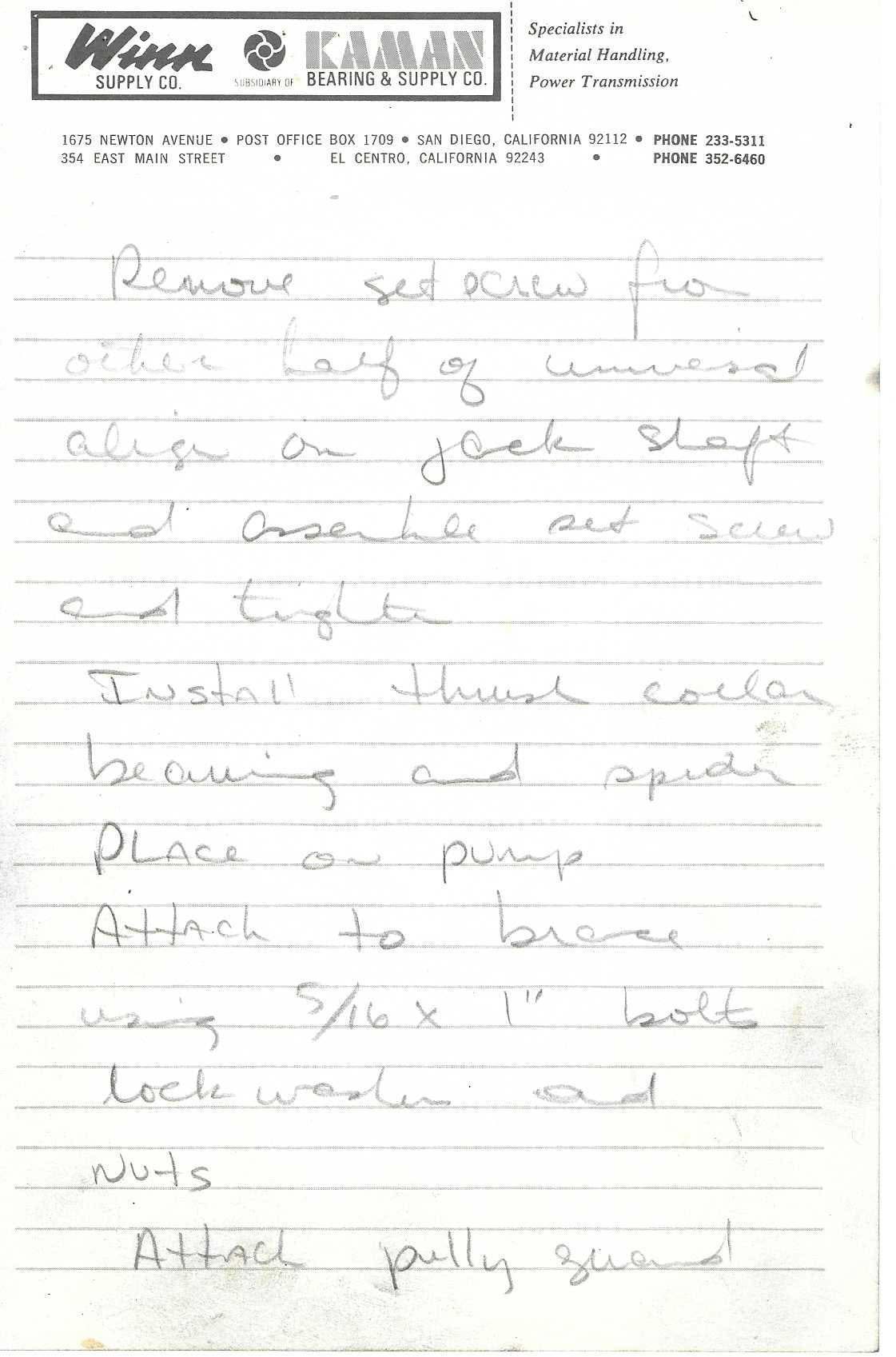
Handwritten note (pencil) on Winn Supply Co. letterhead (same header as p. 26). Scan is cropped short (square). Continuation: universal coupling, thrust collar, pump to brace.
Remove set screw from
other half of universal
align on jack shaft
and assemble set screw
and tighten
Install thrust collar
bearing and spider
Place on pump
Attach to brace
using 5/16 x 1" bolt
lockwasher and
nuts
Attach pully guard
Page 30 of 50
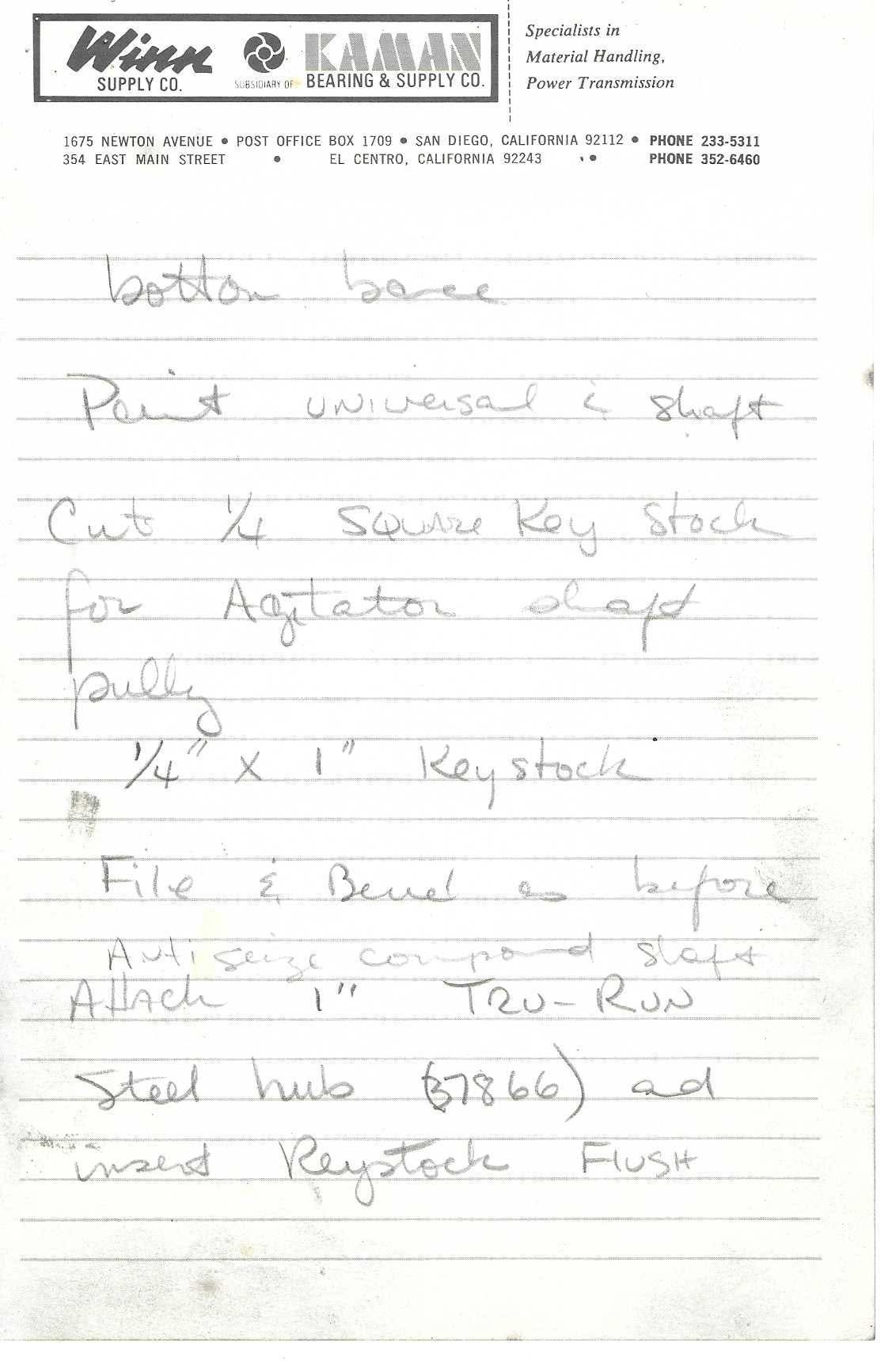
Handwritten note (pencil) on Winn Supply Co. letterhead. Continuation: agitator shaft pulley/hub.
bottom brace
Paint universal & shaft
Cut 1/4 square Key stock
for Agitator shaft
pully
1/4" x 1" Keystock
File & Bend as before
Anti seize compound shaft
Attach 1" TRU-RUN
Steel hub (37866) and
insert Keystock FLUSH
Notes: "Anti seize compound shaft" is squeezed in above the "Attach" line (added later). "37866" = TRU-RUN steel hub part number, 1" bore.
Page 31 of 50
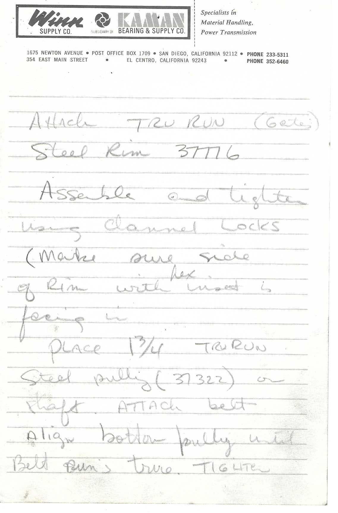
Handwritten note (pencil) on Winn Supply Co. letterhead. Continuation: TRU-RUN (Gates) rim and pulley, agitator belt.
Attach TRU RUN (Gates)
Steel Rim 37776
Assemble and tighten
using Channel Locks
(Make sure side
of Rim with hex insert is
facing in
PLACE 1 3/4 TRU RUN
Steel pully (37322) on
shaft. ATTACH belt
align bottom pully until
Belt Run's true. TIGHTEN
Notes: "hex" is inserted above "insert" with a caret. Part numbers: TRU-RUN (Gates) steel rim 37776; 1 3/4 TRU-RUN steel pulley 37322.
Page 32 of 50
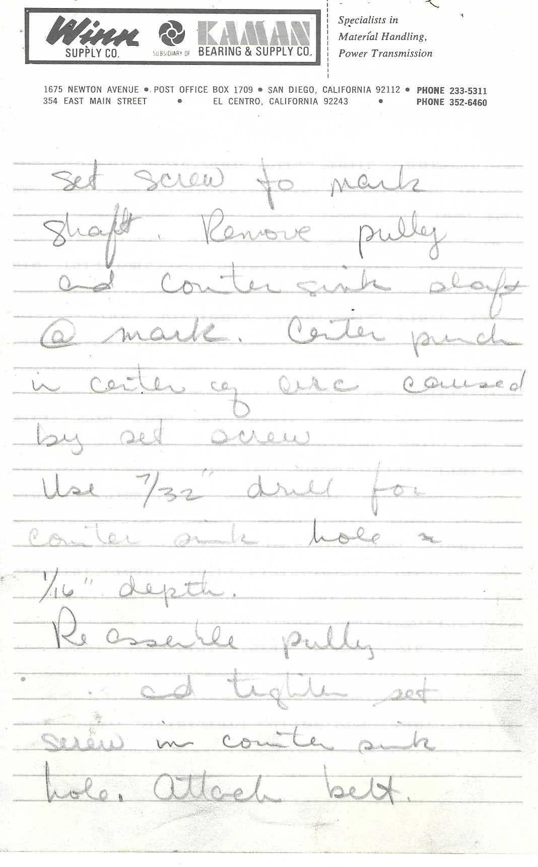
Handwritten note (pencil) on Winn Supply Co. letterhead (scan cropped to the sheet width). Continuation: locating the pulley set screw with a countersink in the shaft.
set screw to mark
shaft. Remove pulley
and Counter sink shaft
@ mark. Center punch
in center of arc caused
by set screw
Use 7/32" drill for
Counter sink hole x
1/16" depth.
Reassemble pully
and tighten set
screw in counter sink
hole. Attach belt.
Page 33 of 50
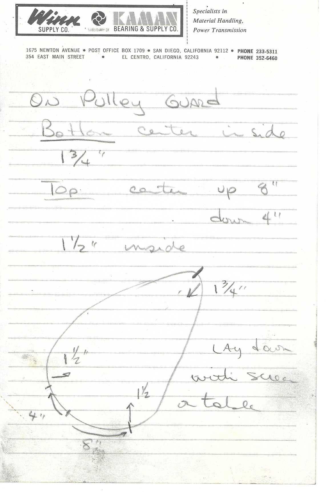
Handwritten note with sketch (pencil) on Winn Supply Co. letterhead. Pulley-guard hole layout.
On Pulley Guard
Bottom center inside ("Bottom" underlined)
1 3/4"
Top center up 8" ("Top" underlined)
down 4"
1 1/2" inside
Sketch: a teardrop/pear-shaped outline (the pulley-guard outline, narrow end up-right, rounded wide end at lower left), drawn freehand. Annotations on the sketch:
- At the top (narrow) end, a tick mark on the outline with an arrow pointing inward labelled "1 3/4"" (hole 1 3/4" in from the edge at the top/narrow end).
- Along the bottom curve, a curved arrow labelled "8"" running from a tick at the lower-left to a tick at the lower-right of the rounded end; at the lower-right tick an inward (upward) arrow labelled "1 1/2".
- On the left side, a curved arrow labelled "4"" running up from a tick at the lower-left to another tick on the left side; at that left tick an inward arrow labelled "1 1/2"".
- Beside the sketch: "Lay down with screen [on?] a table".
Interpretation (as written, not added): three hole marks — one at the narrow end 1 3/4" inside; one 8" along the edge from the bottom center, 1 1/2" inside; one 4" along the edge the other way, 1 1/2" inside. Page 34 then says drill (3) holes at the marks.
Page 34 of 50
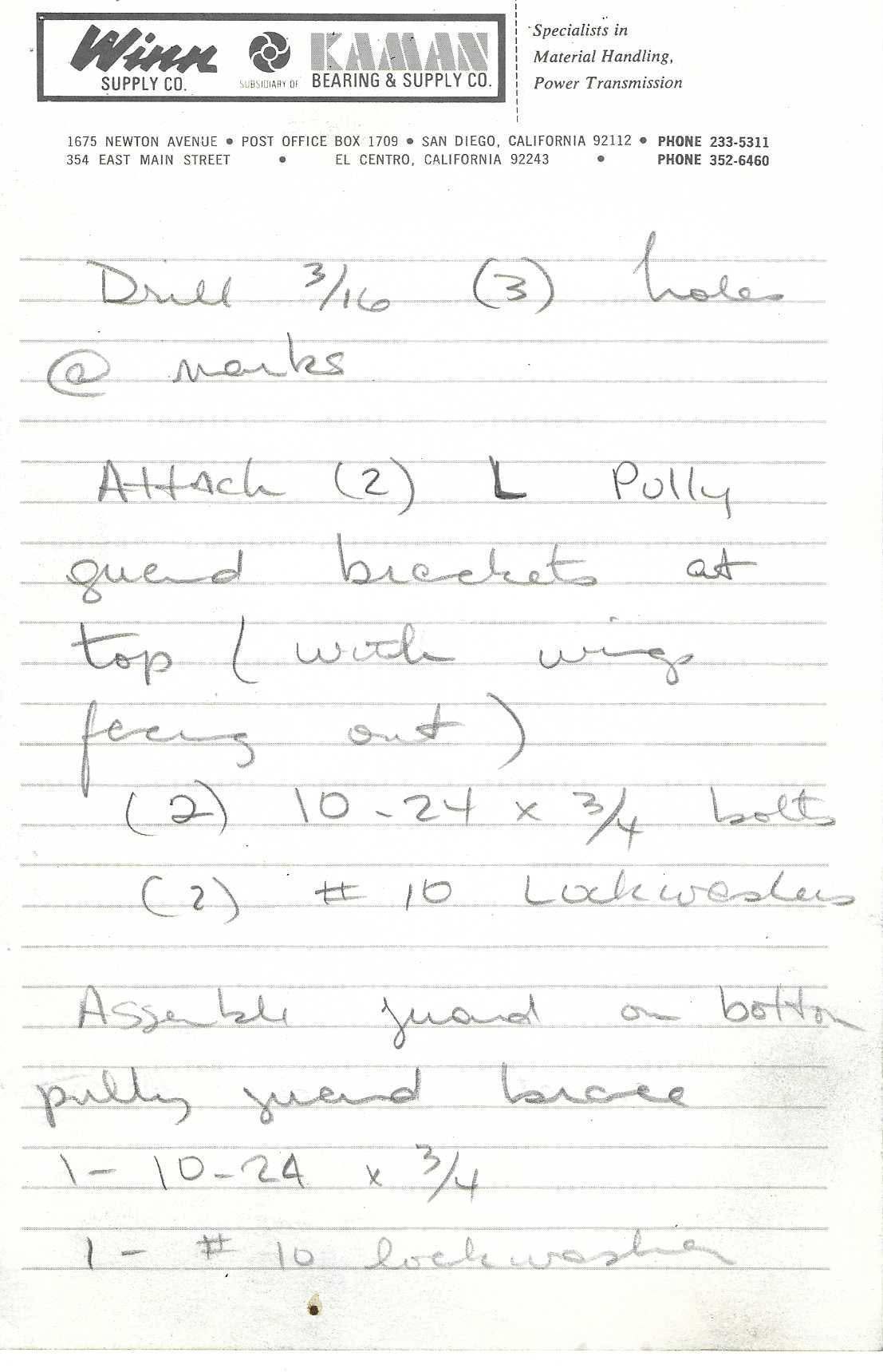
Handwritten note (pencil) on Winn Supply Co. letterhead (cropped to sheet width). Continuation: pulley guard brackets and fasteners.
Drill 3/16 (3) holes
@ marks
Attach (2) L Polly
guard brackets at
top (with wings
facing out)
(2) 10-24 x 3/4 bolts
(2) #10 Lockwashers
Assemble guard on bottom
pully guard brace
1 - 10-24 x 3/4
1 - #10 lockwasher
Page 35 of 50
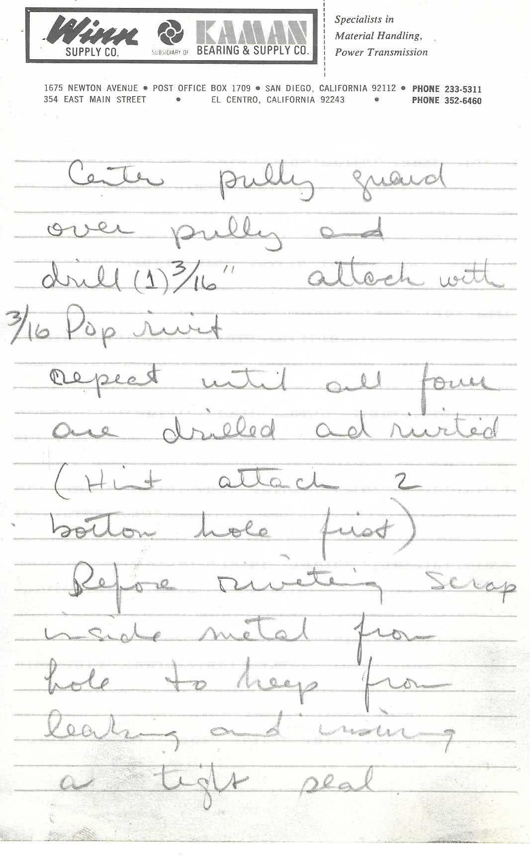
Handwritten note (pencil) on Winn Supply Co. letterhead (cropped to sheet width). Continuation: riveting the pulley guard.
Center pully guard
over pully and
drill (1) 3/16" attach with
3/16 Pop rivet
Repeat until all four
are drilled and rivited
(Hint attach 2
bottom hole first)
Before riveting Scrap[e]
inside metal from
hole to keep from
leaking and insuring
a tight seal
Page 36 of 50
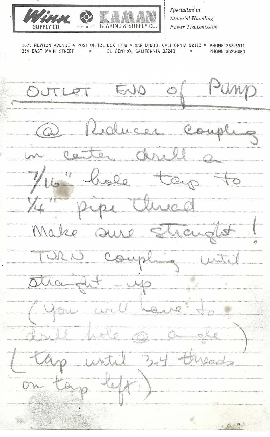
Handwritten note (pencil) on Winn Supply Co. letterhead (cropped to sheet width; some stains). Pump outlet plumbing.
OUTLET END of PUMP (underlined)
@ Reducer coupling
in center drill a
7/16" hole tap to
1/4" pipe thread
Make sure straight!
TURN coupling until
straight - up
(You will have to
drill hole @ angle)
(tap until 3-4 threads
on tap left)
Page 37 of 50
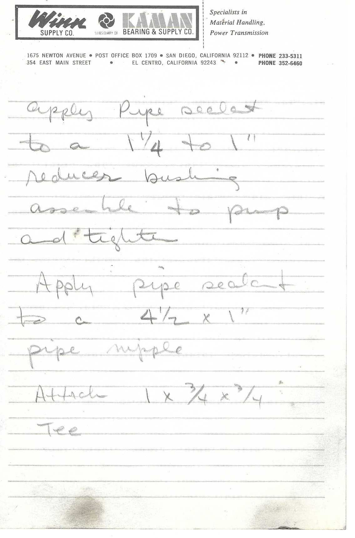
Handwritten note (pencil) on Winn Supply Co. letterhead. Continuation of outlet plumbing.
apply Pipe sealant
to a 1 1/4 to 1"
reducer bushing
assemble to pump
and tighten
Apply pipe sealant
to a 4 1/2 x 1"
pipe nipple
Attach 1 x 3/4 x 3/4
Tee
Page 38 of 50
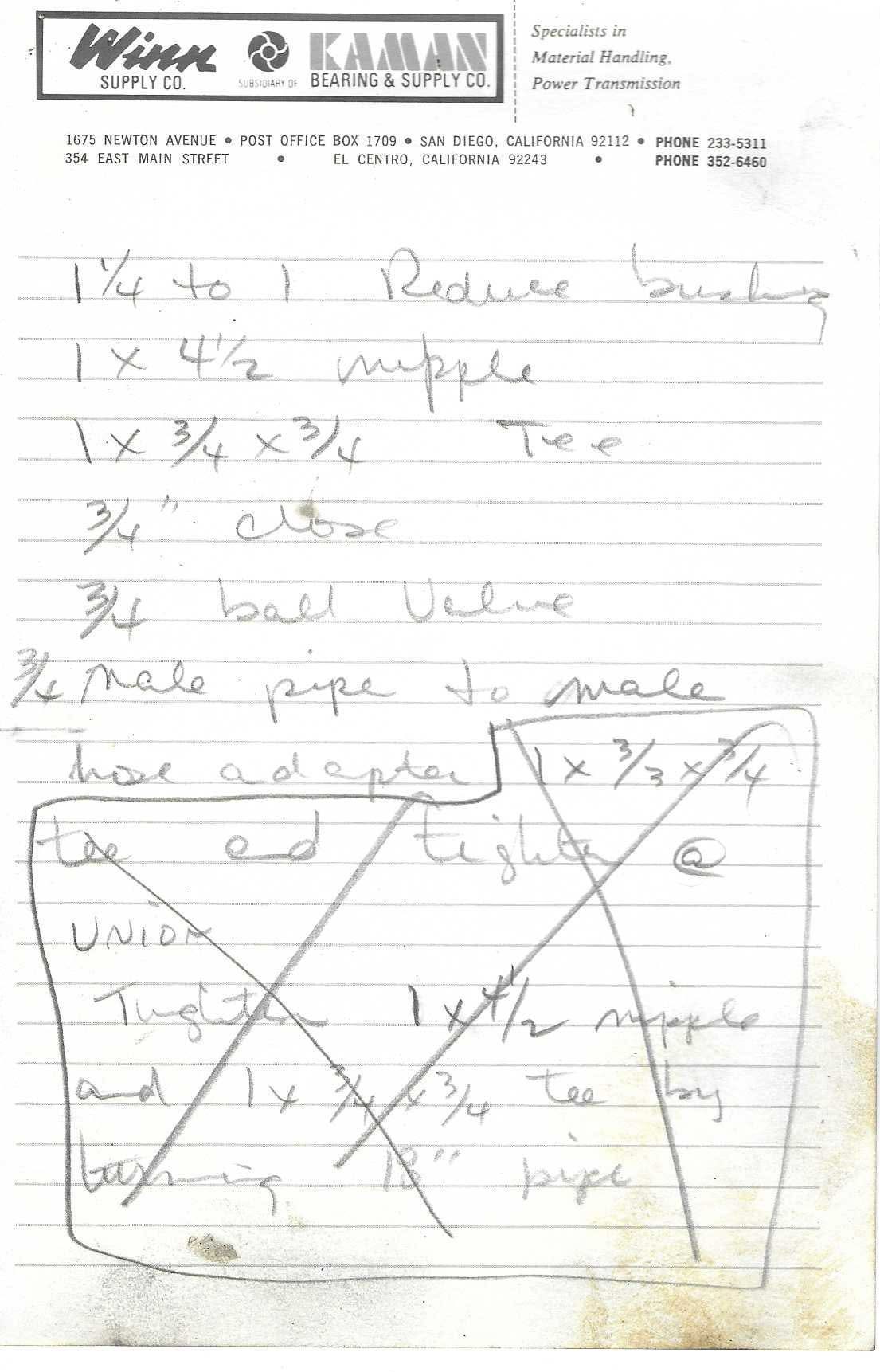
Handwritten note (pencil) on Winn Supply Co. letterhead (cropped to sheet width; staining lower right). Outlet plumbing parts list; lower half boxed and crossed out with a large X (superseded, rewritten on p. 39).
1 1/4 to 1 Reduce[r] bushing
1 x 4 1/2 nipple
1 x 3/4 x 3/4 Tee
3/4" close [nipple]
3/4 ball Valve
3/4 male pipe to male
hose adapter
Crossed-out boxed block (struck through with an X, still legible):
1 x 3/3 x 3/4 [sic — "3/3" as written; presumably 3/4]
tee and tighten @
UNION
Tighten 1 x 4 1/2 nipple
and 1 x 3/4 x 3/4 tee by
turning 18" pipe
Page 39 of 50
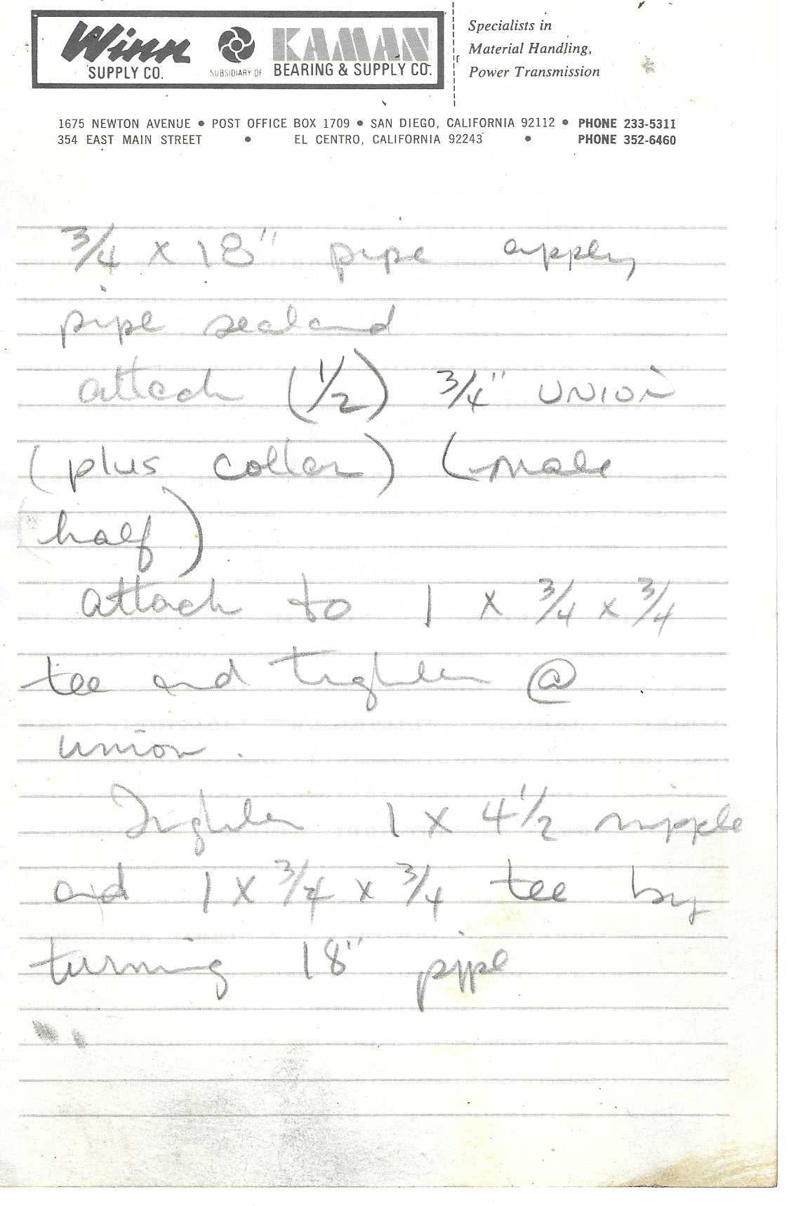
Handwritten note (pencil) on Winn Supply Co. letterhead. Continuation of outlet plumbing (clean rewrite of the struck block on p. 38).
3/4 x 18" pipe apply
pipe sealant
attach (1/2) 3/4" UNION
(plus collar) (male
half)
attach to 1 x 3/4 x 3/4
tee and tighten @
union.
Tighten 1 x 4 1/2 nipple
and 1 x 3/4 x 3/4 tee by
turning 18" pipe
Page 40 of 50
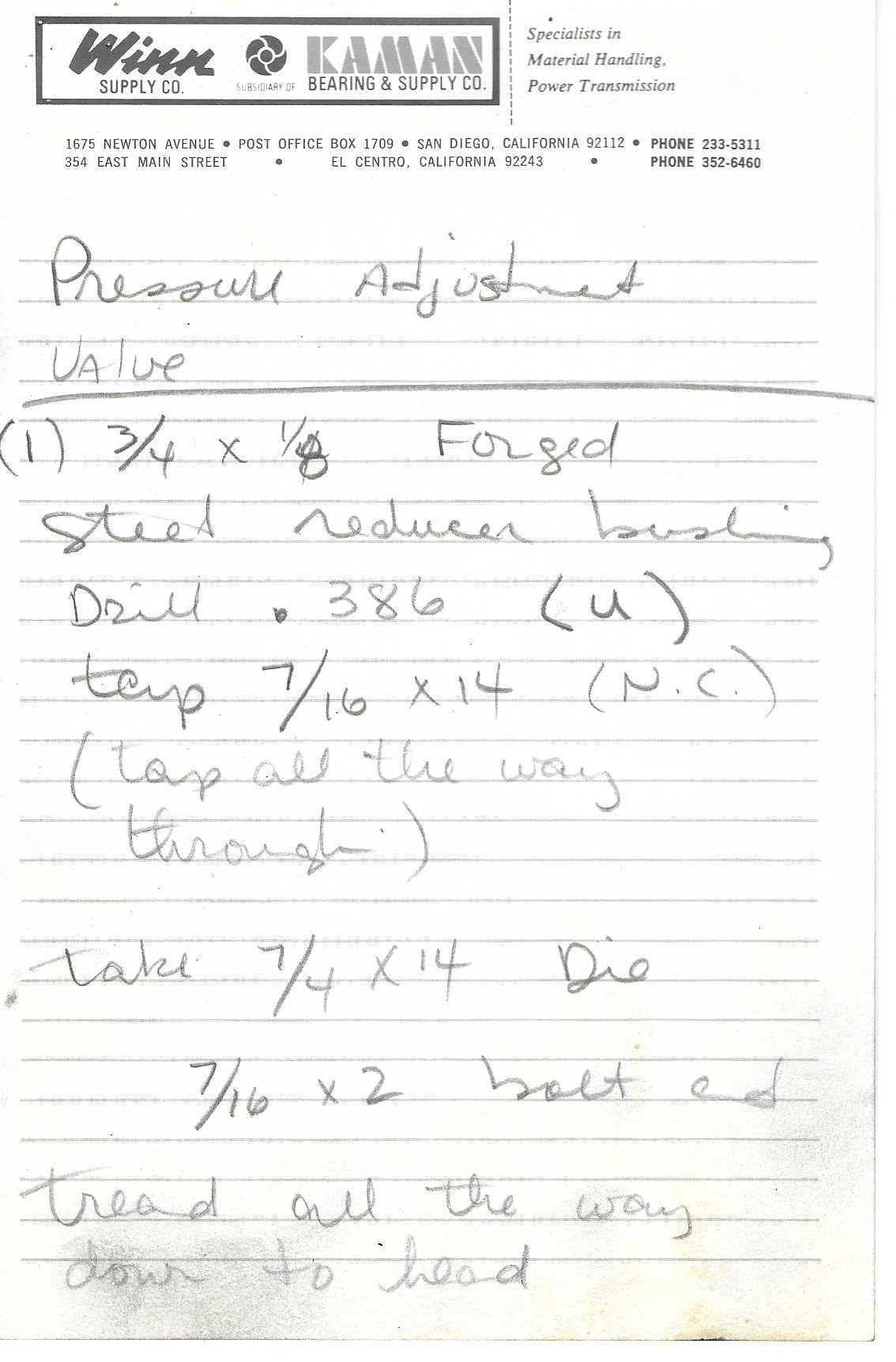
Handwritten note (pencil) on Winn Supply Co. letterhead. Fabrication of the pressure adjustment valve.
Pressure Adjustment
Valve (heading, underlined)
(1) 3/4 x 1/8 Forged
steel reducer bushing
Drill .386 (U)
tap 7/16 x 14 (N.C.)
(tap all the way
through)
take 7/4 x 14 Die [sic — as written "7/4"; presumably 7/16 x 14]
7/16 x 2 bolt and
tread all the way
down to head
Notes: the "8" in "1/8" appears written over another digit [1/8?]. ".386 (U)" = letter-size drill U (0.368" nominal; written as .386). "7/16 x 14 (N.C.)" = 7/16"-14 UNC thread.
Page 41 of 50
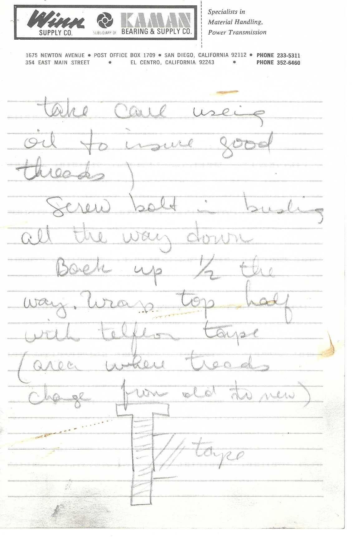
Handwritten note with small sketch (pencil) on Winn Supply Co. letterhead. Continuation of pressure adjustment valve (threading the bolt).
take care useing
oil to insure good
threads )
Screw bolt in bushing
all the way down
Back up 1/2 the
way. Wrap top half
with telflon [teflon] tape
(area where treads
change from old to new)
Sketch: side view of a hex/cap bolt drawn as a "T" — head at top, shank below with diagonal thread hatching along the full length. A bracket on the right side marks a band roughly in the upper-middle of the shank with diagonal hatch lines and the label "tape" (the region to wrap with Teflon tape). No dimensions shown.
Page 42 of 50
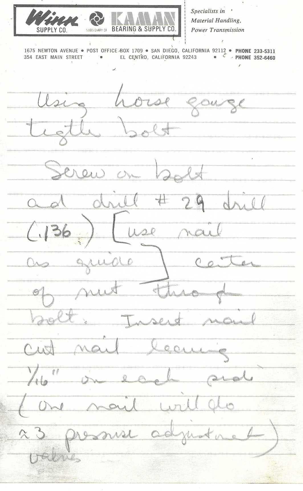
Handwritten note (pencil) on Winn Supply Co. letterhead (cropped to sheet width). Continuation of pressure adjustment valve.
Using horse gouge [horseshoe gauge?]
tighten bolt
Screw on bolt
and drill #29 drill
(.136) [use nail
as guide] center
of nut through
bolt. Insert nail
cut nail leaving
1/16" on each side
(one nail will do
≈3 pressure adjustment
valves)
Notes: "[use nail as guide]" is enclosed in a hand-drawn bracket in the original. "horse gouge" corresponds to the "horse shoe template" on p. 43.
Page 43 of 50
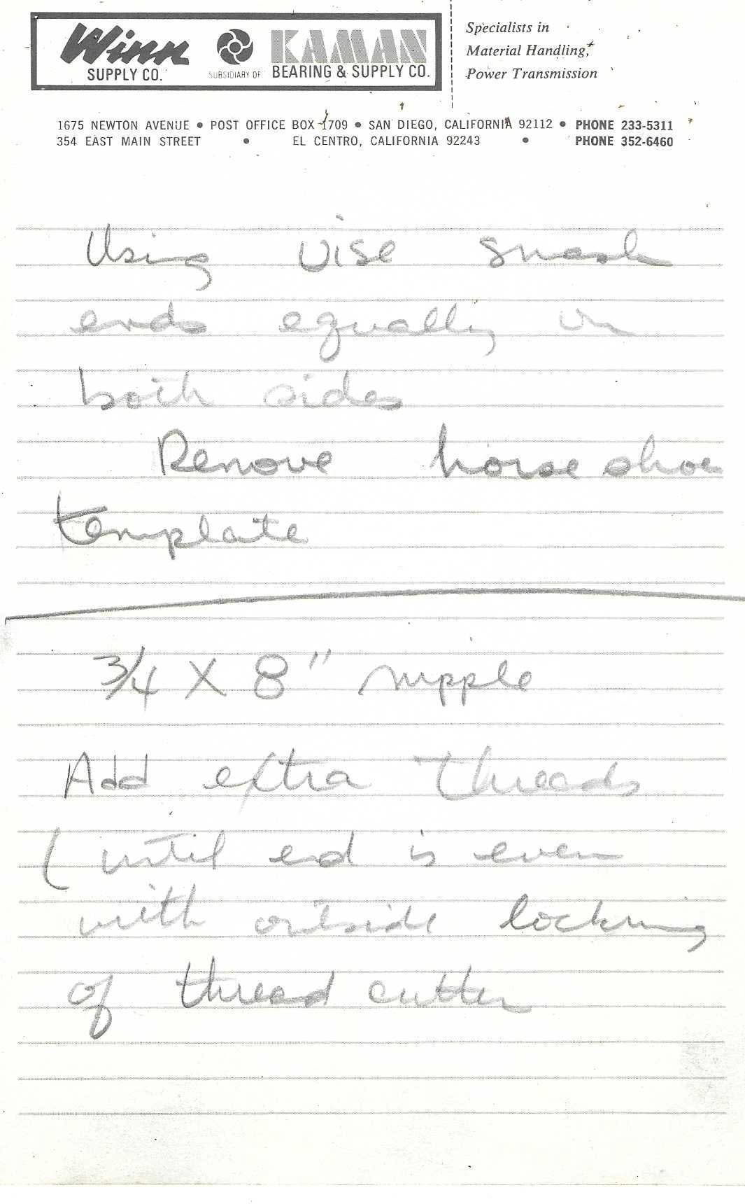
Handwritten note (pencil) on Winn Supply Co. letterhead (cropped to sheet width). Two sections separated by a horizontal rule.
Using Vise smash
ends equally on
both sides
Remove horse shoe
template
————
3/4 X 8" nipple
Add extra threads
(until end is even
with outside locking
of thread cutter
Page 44 of 50
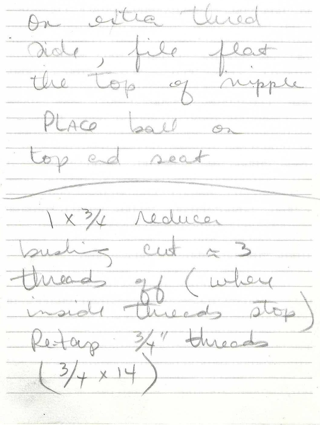
Handwritten note (pencil) on Winn Supply Co. letterhead (scan cropped short and narrow). Pressure adjustment (relief/check) valve: ball seat and reducer bushing. Two sections separated by a hand-drawn line.
On extra thread
side, file flat
the top of nipple
PLACE ball on
top and seat
————
1 x 3/4 reducer
bushing cut ≈ 3
threads off (where
inside threads stop)
Re-tap 3/4" threads
(3/4 x 14)
Page 45 of 50
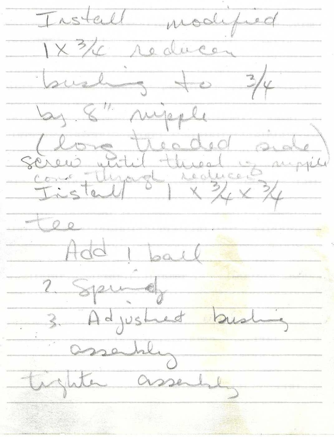
Handwritten note (pencil) on Winn Supply Co. letterhead (cropped short and narrow; staining). Assembly of pressure adjustment valve.
Install modified
1 X 3/4 reducer
bushing to 3/4
by 8" nipple
(long treaded side)
screw until thread of nipple
come through reducer
Install 1 x 3/4 x 3/4
tee
Add 1. ball
2. Spring
3. Adjusted bushing
assembly
tighten assembly
Notes: "screw until thread of nipple come through reducer" is squeezed in between lines (added later).
Page 46 of 50
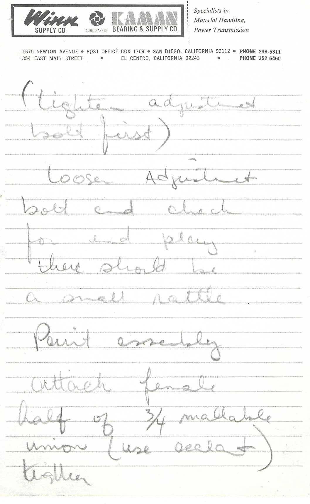
Handwritten note (pencil) on Winn Supply Co. letterhead (cropped to sheet width). Continuation: adjusting and finishing the pressure adjustment valve.
(tighten adjustment
bolt first)
Loosen Adjustment
bolt and check
for end play
there should be
a small rattle
Paint assembly
attach female
half of 3/4 mallable
union (use sealant)
tighten
Page 47 of 50
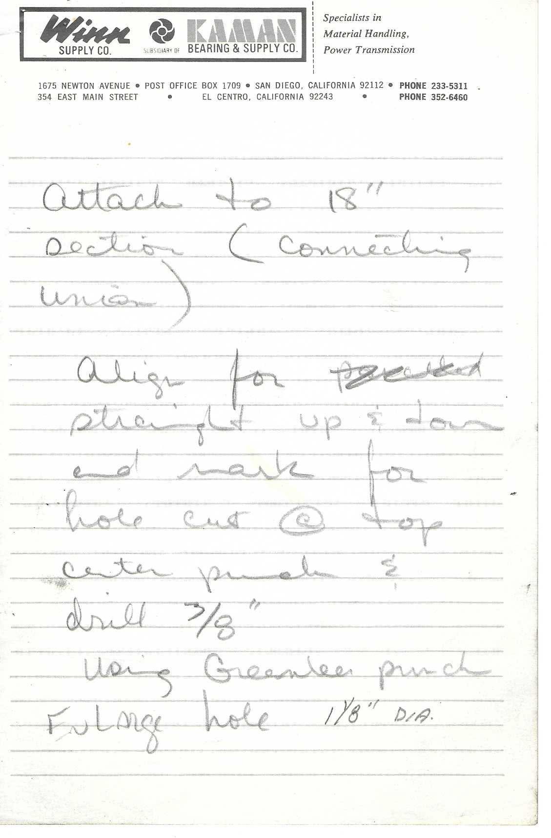
Handwritten note (pencil) on Winn Supply Co. letterhead. Mounting the valve/plumbing through the tank top.
attach to 18"
section (connecting
union)
Align for[parallel?](crossed out)
straight up & down
and mark for
hole cut @ top
center punch &
drill 3/8"
Using Greenlee punch
Enlarge hole 1 1/8" DIA.
Page 48 of 50
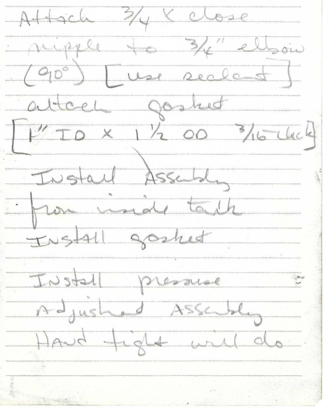
Handwritten note (pencil) on Winn Supply Co. letterhead (scan cropped short). Tank penetration fittings and gasket.
Attach 3/4 x close
nipple to 3/4" elbow
(90°) [use sealant]
attach gasket
[1" ID x 1 1/2 OD 3/16 thick]
Install Assembly
from inside tank
Install gasket
Install pressure
Adjusted Assembly
Hand tight will do
Notes: a stray pencil line runs from the gasket bracket down toward "Assembly". Gasket spec: 1" ID x 1 1/2" OD x 3/16" thick.
Page 49 of 50
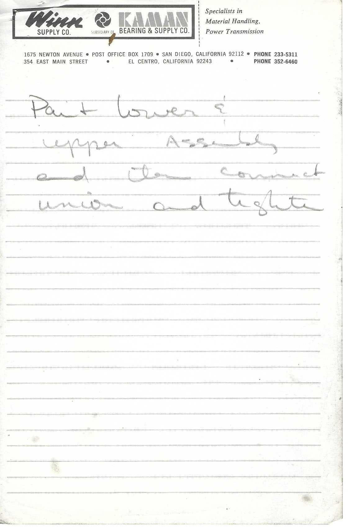
Handwritten note (pencil) on Winn Supply Co. letterhead (scan cropped short). Only four lines; rest of sheet blank.
Paint lower &
upper Assembly
and then connect
union and tighten
Page 50 of 50
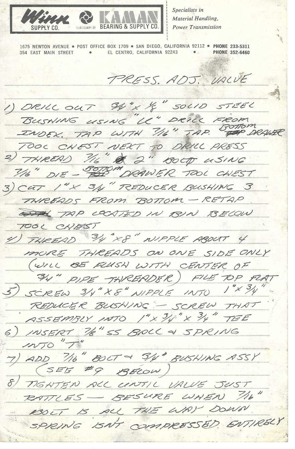
Handwritten note in a different hand: neat block capitals in pen/pencil, on Winn Supply Co. letterhead. A numbered procedure for the pressure adjustment valve that restates pp. 40–46 with extra detail and shop locations of tools. Ends at step 8; step 9 is referred to but is not on this page.
PRESS. ADJ. VALVE
1) DRILL OUT 3/4" x 1/8" SOLID STEEL
BUSHING USING "U" DRILL FROM
INDEX. TAP WITH 7/16" TAP. BOTTOM DRAWER
TOOL CHEST NEXT TO DRILL PRESS
2) THREAD 7/16"x2" BOLT USING
7/16" DIE - BOTTOM DRAWER TOOL CHEST
3) CUT 1" x 3/4" REDUCER BUSHING 3
THREADS FROM BOTTOM - RETAP
[word]TAP LOCATED IN BIN BELOW
TOOL CHEST
4) THREAD 3/4" x 8" NIPPLE ABOUT 4
MORE THREADS ON ONE SIDE ONLY
(WILL BE FLUSH WITH CENTER OF
3/4" PIPE THREADER) FILE TOP FLAT
5) SCREW 3/4" x 8" NIPPLE INTO 1" x 3/4"
REDUCER BUSHING - SCREW THAT
ASSEMBLY INTO 1" x 3/4" x 3/4" TEE
6) INSERT 7/8" SS BALL & SPRING
INTO "T"
7) ADD 7/16" BOLT & 3/4" BUSHING ASSY
(SEE #9 BELOW)
8) TIGHTEN ALL UNTIL VALVE JUST
RATTLES - BESURE WHEN 7/16"
BOLT IS ALL THE WAY DOWN
SPRING ISN'T COMPRESSED ENTIRELY
Notes: In step 1, "TOP" was struck and "BOTTOM" written above it; in step 2, a struck word ("TOP"? / "BO") was replaced by "BOTTOM" written above; in step 3 a word before "TAP" is scribbled out [illegible]. "SS BALL" = stainless steel ball, 7/8". This page confirms the bushing on p. 40 is 3/4" x 1/8".