Polaroid build guide
Twelve notebook pages from the Jetspray shop, each with Polaroid photographs taped on and hand-lettered stickers, covering painting, the agitator, shafts, bearings, leg braces, lid and pump.
About this transcription
Format of the original: hand-written pencil notes on 3-hole lined notebook paper, each page carrying one or two Polaroid (Polacolor 2) photos taped on, with pink circular sticker annotations hand-lettered onto some photos. Most pages carry a round white sticker with a hand-written page number ("-1-" etc.) at top center. Spelling is reproduced as written (e.g. "Pully", "Dissassemble", "vise/vise"). Red ink is used in some sketches to show the bearing. [?] = uncertain reading, [illegible] = cannot be read.
It is a shop procedure for finishing / assembling a Jetspray machine (painting the tank, building the agitator, fitting shafts and bearings, leg braces, lid, pump, reducer bushing).
Transcriber's summary
- Document nature: An in-house, hand-written, Polaroid-illustrated build/finishing procedure for the Airless Jetspray, apparently used to train shop helpers (two different workers pictured). Not a factory-printed manual.
- Sequence: (1) paint tank (bottom later on stand); (2) remove pump legs, paint, prep L/R leg braces; (3) drill tank end plates for bearing flanges using a clamped drill guide (4 × 7/16" holes + 3/8" center enlarged with a 1" Greenlee punch); (4) build agitator (rubber wipers + 11×2 wire screens on 3 wings, 10-24 stove bolts, heads leading in rotation direction); (5) make 1"×12" (pulley side, keyed) and 1"×10" stub shafts, countersink 7/32"; (6) fit Fafnir RCJC 1" flange bearings with grease fittings up, rubber washers; (7) bolt bearings to tank ends with 7/16 × 1-1/4 bolts and copper washers (heads inside); (8) position agitator center blade down over outlet, pin agitator to shafts ~1" from agitator end with 1/4" bolts; (9) rivet leg braces / lid stays at the tank lip (1/4 × 1-1/2 rivets); (10) lid stays with 3/16" pop rivets; (11) align pump on frame with template; (12) make reducer bushing with 9×9 screen.
- Numeric specs found: 1/4" hole (leg brace bottom hole, lip hole, final agitator pin hole); ≈14" (center of top edge of tank – drill guide location); 7/16" (4 outside holes), 3/8" (center hole), 1" Greenlee punch; 10-24 (alt. 8-32) stove bolts, (4) 10-24 nuts; screen 11×2 holes; 1"×12" and 1"×10" shafts; 7/32" countersink drill; Fafnir RCJC 1" bearing; (4) 7/16×1-1/4 bolts, (4) 7/16 copper washers, snug + 1/2 turn; 1/8" pilot → 1/4" final pin hole ≈1" from agitator end; 1/4×1-3/4 (or 1/4×2) bolts; 1/4×1-1/2 (or 1/4×1-1/4) rivets; 3/16" drill for lid; reducer bushing tap 3/16 [or 1/4]-24 [uncertain]; 9×9 screen.
- Geometry facts: tank end plates have a semicircular bottom (curved weld seam); tank top has an outward lip; agitator = long bar with a center wing on one side and two outside blades on the other, rotating "away from you"; bearings are 4-bolt square-flange units on the outside of each end plate; outlet hole is at the bottom center of the tank; 12" shaft on the pulley side.
- Unknowns: no overall tank dimensions, sheet gauge, frame member sizes, or agitator radius are given; page 11 text is truncated.
Page 1 of 12
(sticker "-1-")
Text (right of top photo):
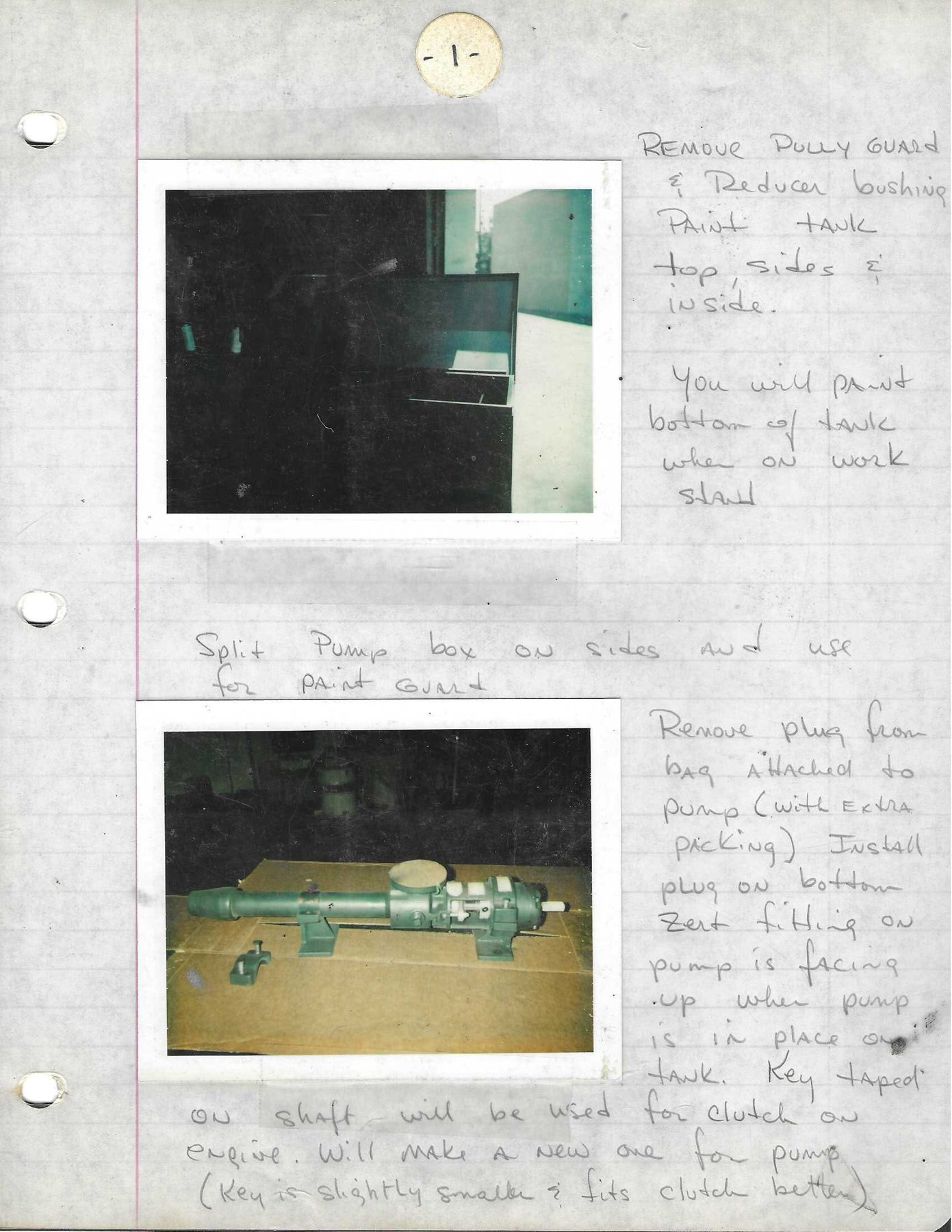
REMOVE PULLY GUARD & Reducer bushing
PAINT TANK top, sides & inside.You will paint bottom of tank when on work stand
Text (between photos):
Split Pump box on sides and use for paint guard
Text (right of / below bottom photo):
Remove plug from bag attached to pump (with extra packing) Install plug on bottom. Zert fitting on pump is facing up when pump is in place on tank. Key taped on shaft will be used for clutch on engine. Will make a new one for pump (Key is slightly smaller & fits clutch better)
Photo 1 (top): The bare tank, seen from above/one end, in a dark shop with daylight from an open doorway at right. The tank is a dark (dark green / near-black in the print) sheet-steel box-like body with its lid hinged open toward the back; the open lid is a flat rectangular sheet with turned-down edges. The inside of the tank is visible at lower right (lighter interior wall). Two small cylindrical objects (light-colored) hang at left (unidentified, possibly spray cans or tags). No frame, engine or pump fitted yet.
Photo 2 (bottom): The pump as received, lying on flattened cardboard. Dark green painted cast-iron rotary pump with: a long horizontal discharge pipe on the left ending in a larger-diameter stepped/reducing fitting (left end), a pipe-saddle support foot under the pipe; the pump body near center-right with a round flanged inlet (a circular disc/flange facing up, appears covered with a cardboard/paper disk) on top; to the right, the bearing bracket / stuffing-box area with white tags/tape and a shaft end protruding to the right (white tape on shaft — the taped key). A separate loose pedestal leg/clamp (U-shaped saddle with a bolt) lies in front at left. Overall pump+pipe assembly length estimate: roughly 2.5–3 ft (estimate, from cardboard flap size; no hard scale).
Page 2 of 12
(sticker "-2-")
Text (right of top photo):
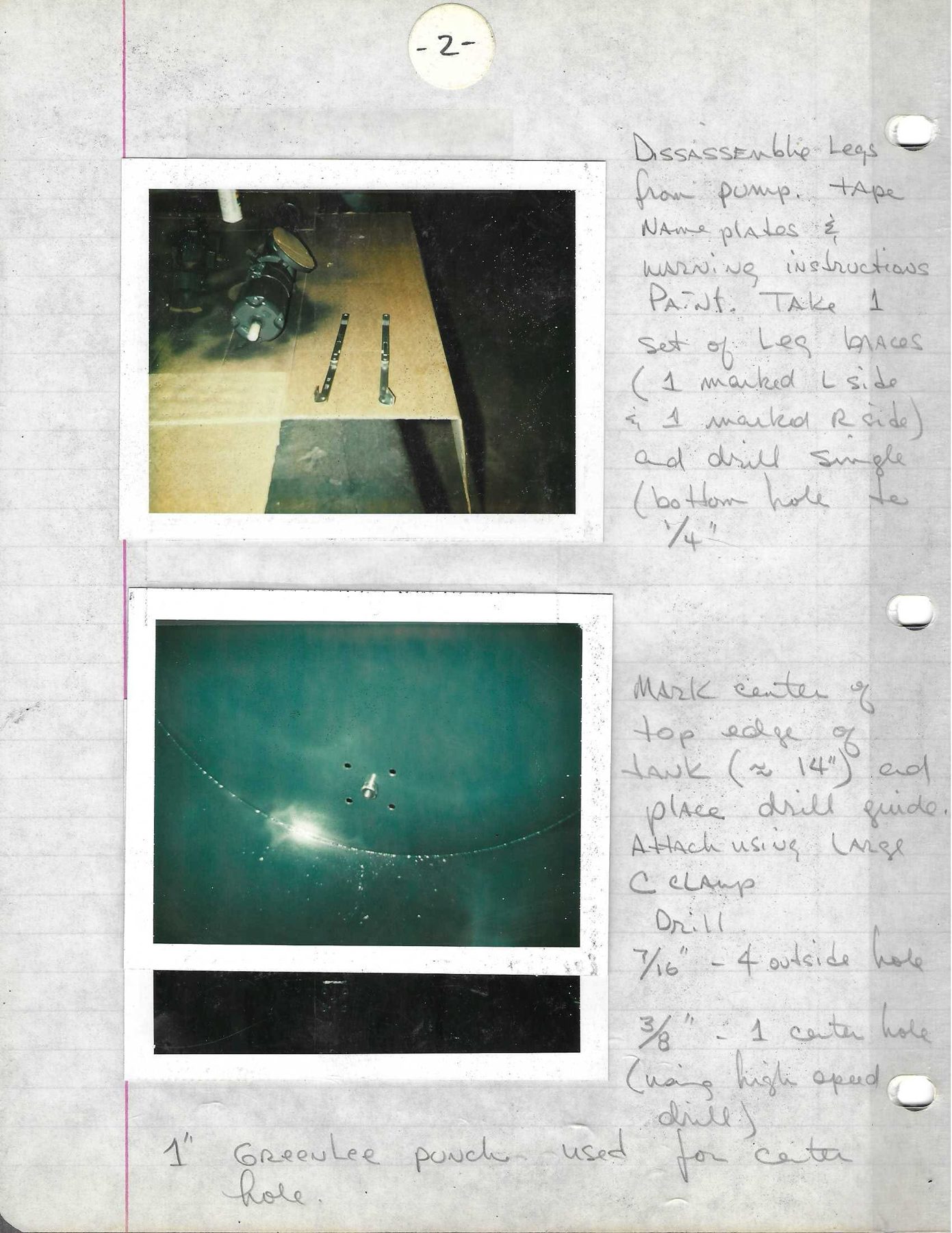
Dissassemble Legs from pump. tape Name plates & warning instructions Paint. TAKE 1 set of Leg braces (1 marked L side & 1 marked R side) and drill single (bottom) hole to 1/4"
Text (right of bottom photo):
MARK center of top edge of tank (≈ 14") and place drill guide. Attach using Large C CLAMP
Drill
7/16" - 4 outside hole
3/8" - 1 center hole (using high speed drill)
Text (bottom):
1" Greenlee punch used for center hole.
Photo 1 (top): On a cardboard-covered bench: the pump (left, dark green, round flanged top inlet with a disc on it, white shaft stub) lying on its side with legs removed; next to it two long flat steel strap leg braces (each with a hooked/bent lower end), lying side by side. Braces look roughly 18–24" long (estimate relative to the pump).
Photo 2 (bottom): Close-up of a tank end plate (dark green). A curved weld seam (the semicircular bottom of the end plate) runs across the lower half. At center: a drill guide / pilot fixture with a short cylindrical boss in the middle and 4 small holes in a square pattern around it (the 4 × 7/16" bolt holes + 1 center hole for the bearing flange). A second (dark, mostly blank) photo strip is stacked below it.
Page 3 of 12
(sticker "-3-")
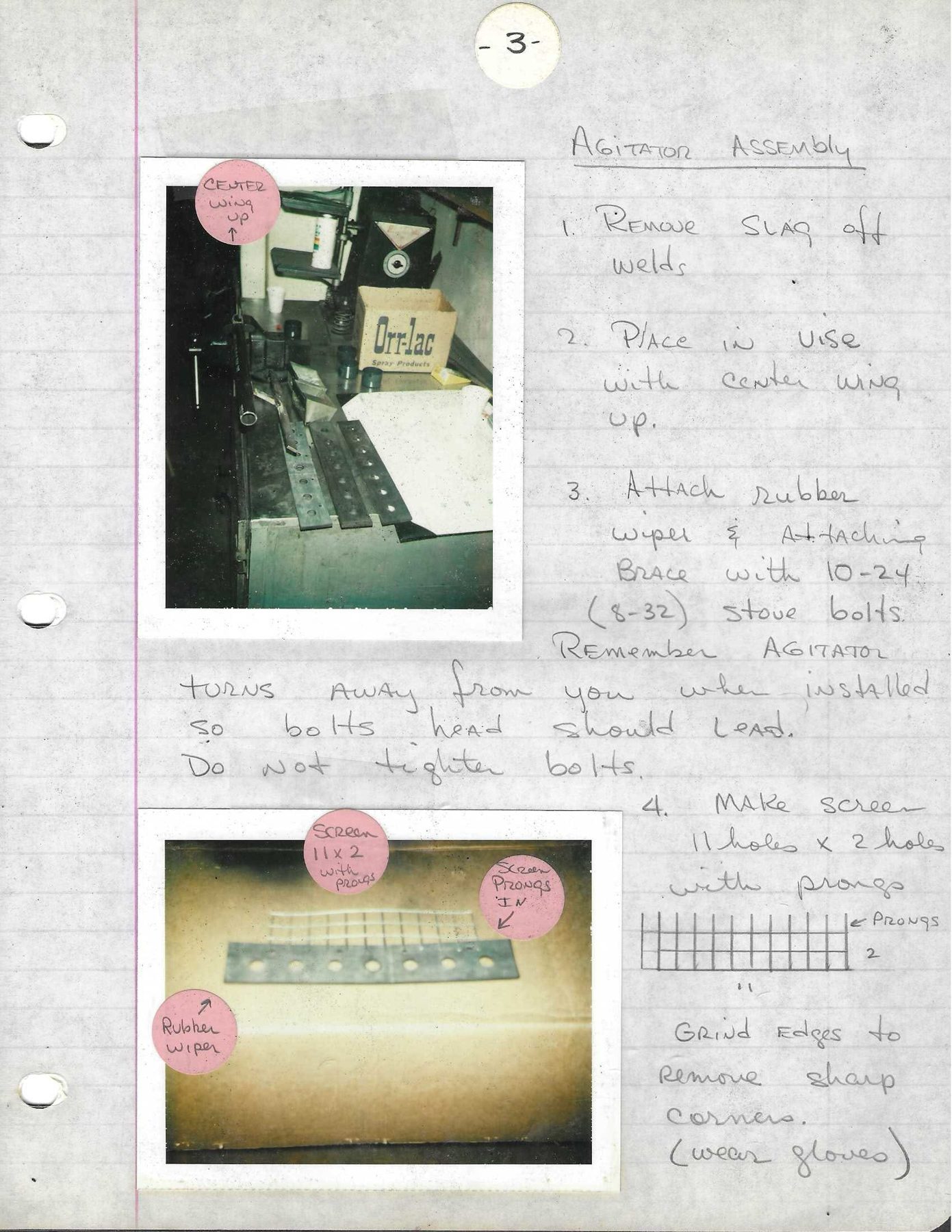
Heading: AGITATOR ASSEMBLY
- Remove Slag off welds
- Place in vise with center wing up.
- Attach rubber wiper & Attaching Brace with 10-24 (8-32) stove bolts. Remember AGITATOR turns away from you when installed so bolts head should Lead. Do not tighten bolts.
- Make screen 11 holes x 2 holes with prongs
[sketch: a grid 11 squares long × 2 squares high, with the prong ends projecting from the top edge; labeled "← PRONGS", "2" on the short side, "11" on the long side]
Grind Edges to remove sharp corners. (wear gloves)
Photo 1 (top), sticker "CENTER wing up ↑": Workbench with a bench vise at left holding the welded agitator frame (long steel bar/angle) on end; three loose rubber wiper strips (flat, dark, each with a row of ~7 round holes) lie on the bench. A carton marked "Orr-lac Spray Products" and spray cans are in the background, plus a coffee cup and a grinder.
Photo 2 (bottom), stickers "Screen 11x2 with prongs", "Screen Prongs IN ↙", "Rubber wiper ↗": A single rubber wiper strip (dark gray rubber, long rectangle, row of 7 round holes along its length) with a welded-wire screen (11 × 2 open squares, wire prongs along one long edge) laid against it. Wiper length estimated at ~2× the screen height × 5; screen roughly as long as the wiper.
Page 4 of 12
(no number sticker visible; sequence implies "-4-")
Text:
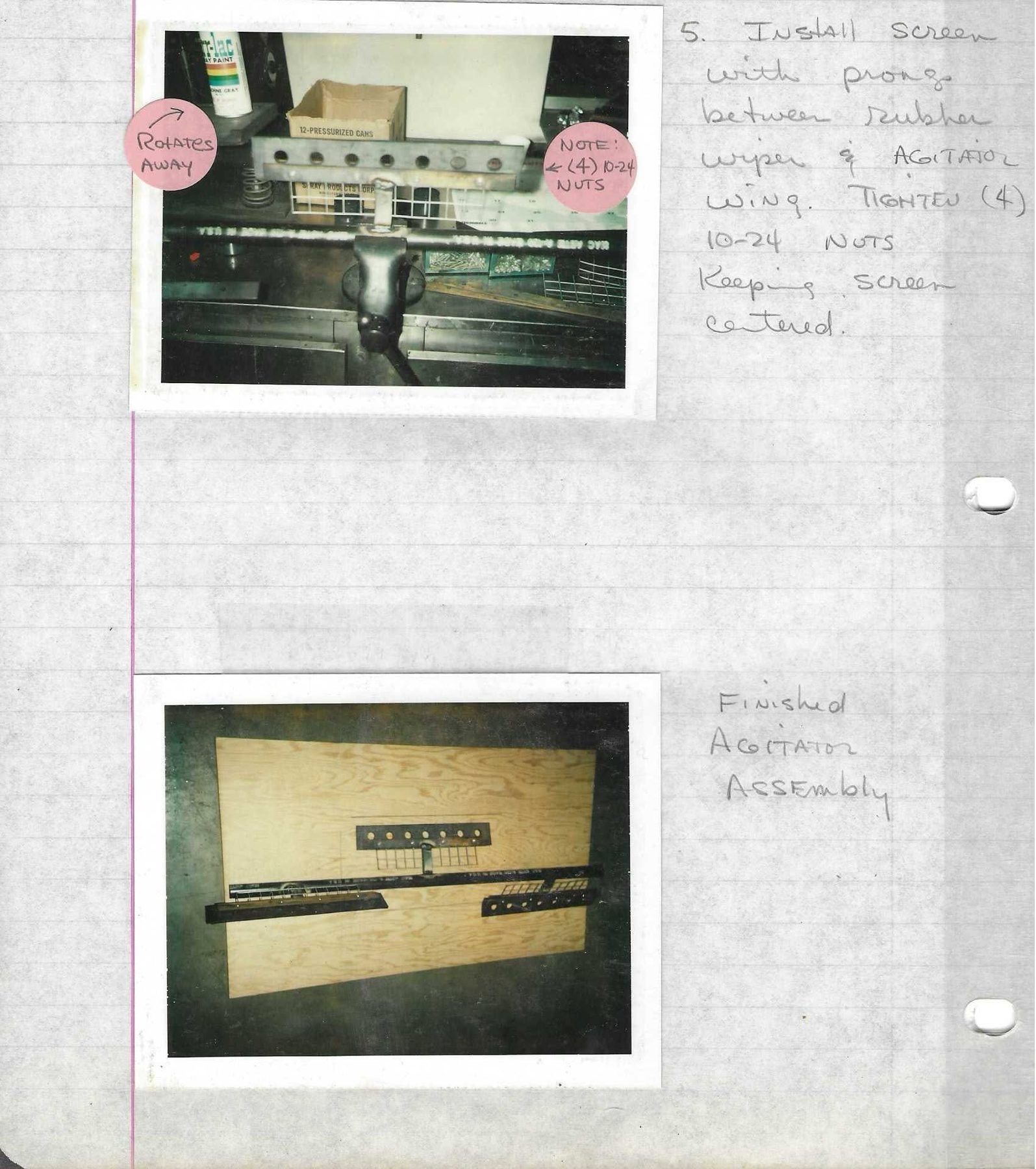
- Install screen with prongs between rubber wiper & AGITATOR wing. TIGHTEN (4) 10-24 NUTS Keeping screen centered.
Finished AGITATOR Assembly
Photo 1 (top), stickers "Rotates AWAY ↗" and "NOTE: ← (4) 10-24 NUTS": Agitator blade clamped in a bench vise: a steel angle wing with a row of 7 round holes (the rubber wiper, holes aligned), the wire screen (prongs) sandwiched below, held by stove bolts. Behind: a box marked "12-PRESSURIZED CANS" and an "…r-lac … PAINT" spray can (Orr-lac).
Photo 2 (bottom): The finished agitator laid on a plywood sheet, viewed from above. Layout: one long central bar (steel angle/flat, full length of the agitator, with stamped lettering along it) running horizontally; at the center, a short perpendicular arm/web rises to the center wing (above the bar), which carries a rubber wiper strip with 7 round holes and a wire screen hanging below it. At each end of the long bar there is an outside blade (left and right), positioned on the opposite side of the bar from the center wing (below the bar line in the photo), each with its own rubber wiper and screen (screens visible with prongs). The left outside blade appears as a long dark angle; the right as a perforated strip with screen. Overall proportion: long bar ≈ 5–6× the center-wing length (estimate). The plywood sheet appears about 4 ft wide, making the agitator roughly 3.5–4 ft long (estimate).
Page 5 of 12
(sticker "-5-")
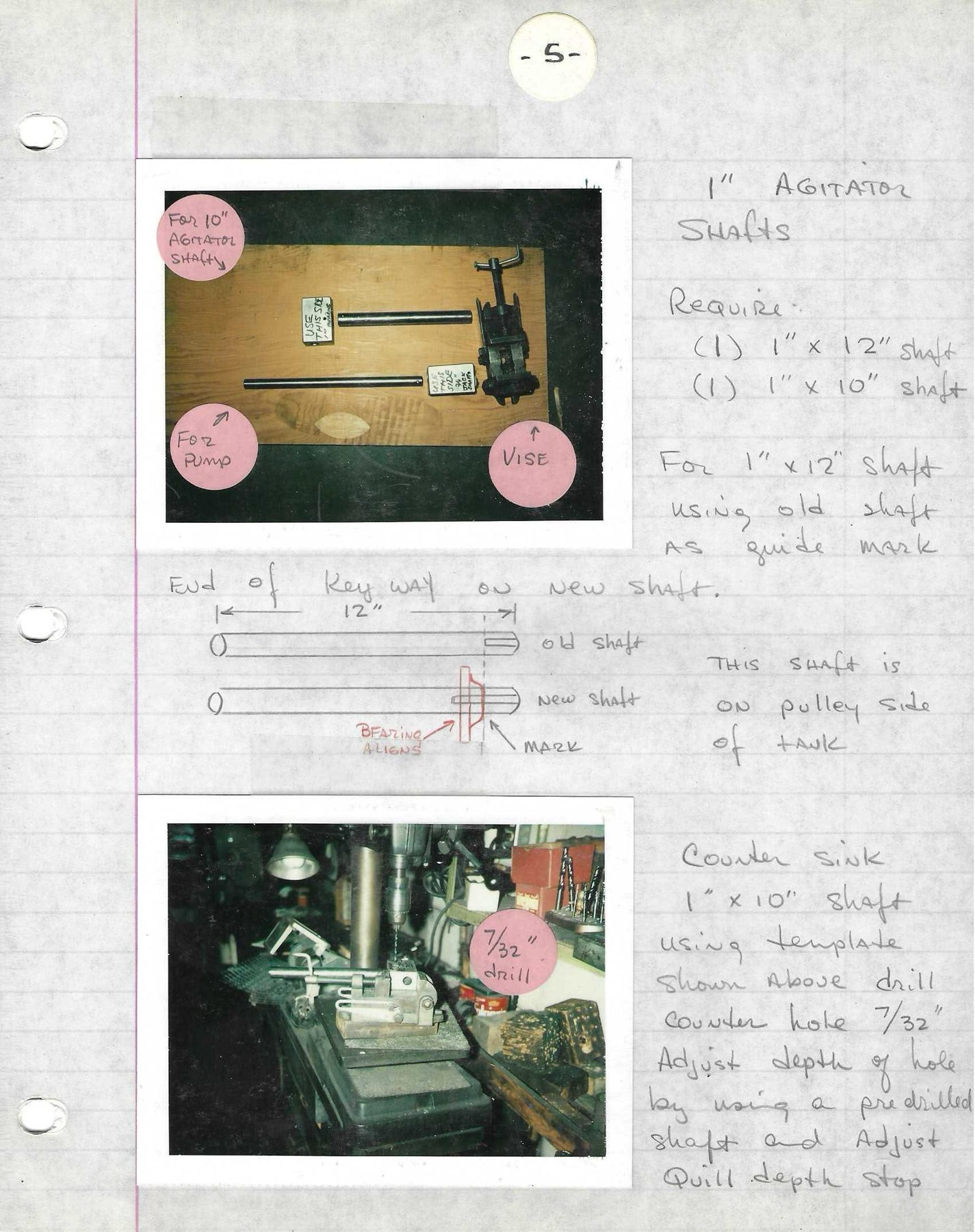
Heading: 1" AGITATOR SHAFTS
Require:
(1) 1" x 12" shaft
(1) 1" x 10" shaftFor 1" x 12" Shaft using old shaft as guide mark End of Key way on new shaft.
Sketch: Two shafts drawn one above the other, ends aligned on the left. Dimension "|← 12" →|" spans the upper shaft. Upper shaft labeled "old shaft", with a keyway at its right end. Lower shaft labeled "new shaft", with a dashed vertical mark line at the end of the old shaft's keyway; a bearing outline drawn in red at that line, labeled (red) "BEARING ALIGNS", and "MARK" with an arrow to the dashed line. The keyway on the new shaft extends to the right of the bearing.
THIS SHAFT is on pulley side of tank
Photo 1, stickers "For 10" AGITATOR shaft", "For PUMP", "VISE ↑": On a wooden board: a small drill vise (right) with a T-handle screw; two plain round steel shafts (one shorter upper, one longer lower), each with a small block-template beside it labeled in marker: upper "USE THIS SIDE [illegible small text]"; lower "USE THIS SIDE [3/4?/24?"] JACK SHAFT[S?]" (reading uncertain). The two templates are drilling jigs.
Text (right of photo 2):
Counter sink 1" x 10" shaft using template shown Above drill counter hole 7/32" Adjust depth of hole by using a predrilled shaft and Adjust Quill depth stop
Photo 2, sticker "7/32" drill": A floor/bench drill press drilling a shaft clamped in a drill-press vise (template on top). Shop clutter: drill-bit index, lamp.
Page 6 of 12
(sticker "-6-")
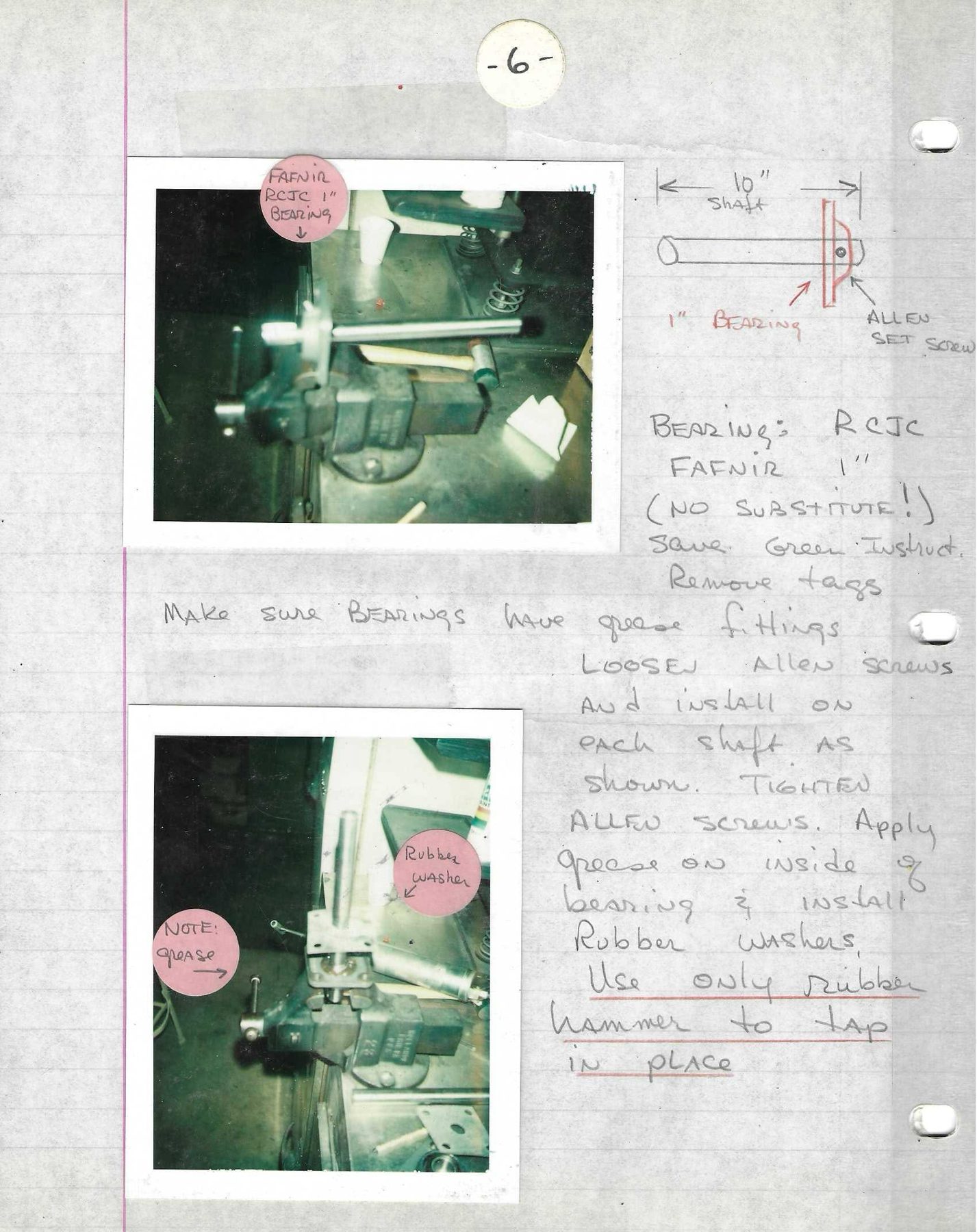
Sketch (top right): A shaft with dimension "|← 10" shaft →|"; near the right end a bearing drawn in red (flange-style outline) labeled (red) "1" BEARING"; a set screw dot on the bearing collar, labeled "ALLEN SET SCREW".
BEARING: RCJC FAFNIR 1" (NO SUBSTITUTE!)
Save Green Instruct. Remove tagsMake sure BEARINGS have grease fittings
LOOSEN Allen screws and install on each shaft as shown. TIGHTEN ALLEN screws. Apply grease on inside of bearing & install Rubber washers. Use only rubber hammer to tap in place (last sentence underlined in red)
Photo 1, sticker "FAFNIR RCJC 1" BEARING ↓": A 1" shaft held vertically/at an angle in a bench vise, with a flanged bearing unit (round-flange cartridge with white collar) near the top end. A wooden-handled mallet lies behind.
Photo 2, stickers "Rubber washer ↙" and "NOTE: grease →": Shaft held vertically in a bench vise with a 4-bolt square-flange bearing unit mounted on it (flange plate square, with 4 corner holes, central bearing insert); grease visible on the bearing face; a rubber washer above.
Page 7 of 12
(sticker "-7-")
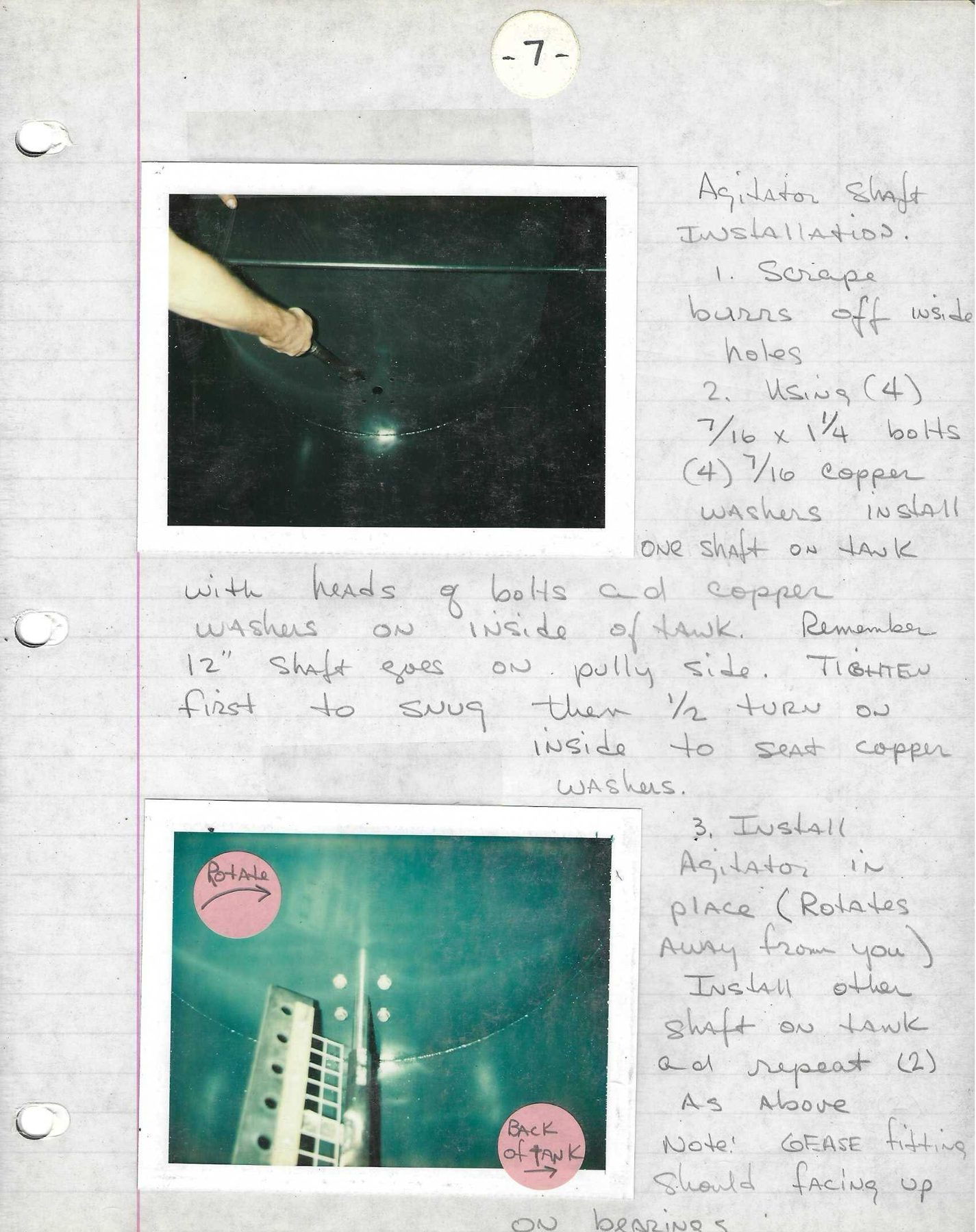
Heading: Agitator Shaft INSTALLATION.
- Scrape burrs off inside holes
- Using (4) 7/16 x 1 1/4 bolts (4) 7/16 copper washers install one shaft on tank with heads of bolts and copper washers on inside of tank. Remember 12" Shaft goes on pully side. TIGHTEN first to snug then 1/2 turn on inside to seat copper washers.
- Install Agitator in place (Rotates Away from you) Install other shaft on tank and repeat (2) As Above
Note! GEASE fitting should facing up on bearings
Photo 1 (top): Looking down into the tank: an arm (hand holding a scraper) reaching to the inside surface of the end plate; the curved bottom weld seam and the bearing-bolt holes (one center hole and smaller holes) are visible. A horizontal ledge/lip line runs across the top of the view (inside edge of tank top).
Photo 2 (bottom), stickers "Rotate →" and "BACK of TANK →": Inside the tank near one end: the agitator end standing upright — a perforated strip (rubber wiper, 5+ round holes) with a wire screen beside it, and the shaft tube; on the end plate behind, 4 bolt heads (with copper washers) in a square around the center (the bearing mounting bolts), with the curved bottom weld seam below.
Page 8 of 12
(sticker "-8-")
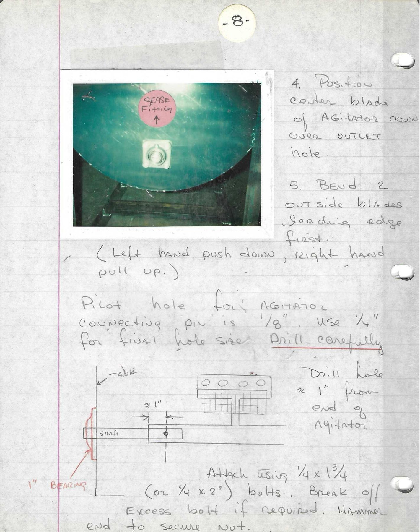
- Position center blade of AGITATOR down over OUTLET hole.
- Bend 2 outside blades leading edge first. (Left hand push down, right hand pull up.)
Pilot hole for AGITATOR connecting pin is 1/8". Use 1/4" for final hole size. Drill carefully (underlined in red)
Sketch: Side elevation. Left: a vertical line labeled "TANK" (the end plate) with a short horizontal at the bottom. The bearing (drawn in red, labeled red "1" BEARING") sits on the outside of the tank wall. A shaft (labeled "SHAFT") passes through the tank wall and into a rectangular sleeve (the agitator end tube); a center-line dot on the sleeve marks the cross-drilled pin hole, dimension "≈ 1"" measured from the inner end of the sleeve (end of agitator) to the hole. Above and to the right: the agitator blade drawn as a box with 4 circles (wiper holes) and a grid screen below it, connected down to the long agitator bar which runs to the right.
Drill hole ≈ 1" from end of Agitator
Attach using 1/4 x 1 3/4 (or 1/4 x 2") bolts. Break off Excess bolt if required. Hammer end to secure nut.
Photo, sticker "GREASE Fitting ↑": End view of the tank, end plate (dark green): the lower edge is a semicircle; below it the frame legs/angle braces are visible. Centered on the end plate is a square-flanged bearing (4-bolt square flange, light colored/plated) with the round bearing insert and shaft end; the grease fitting is above it (arrow).
Page 9 of 12
(sticker "-9-")
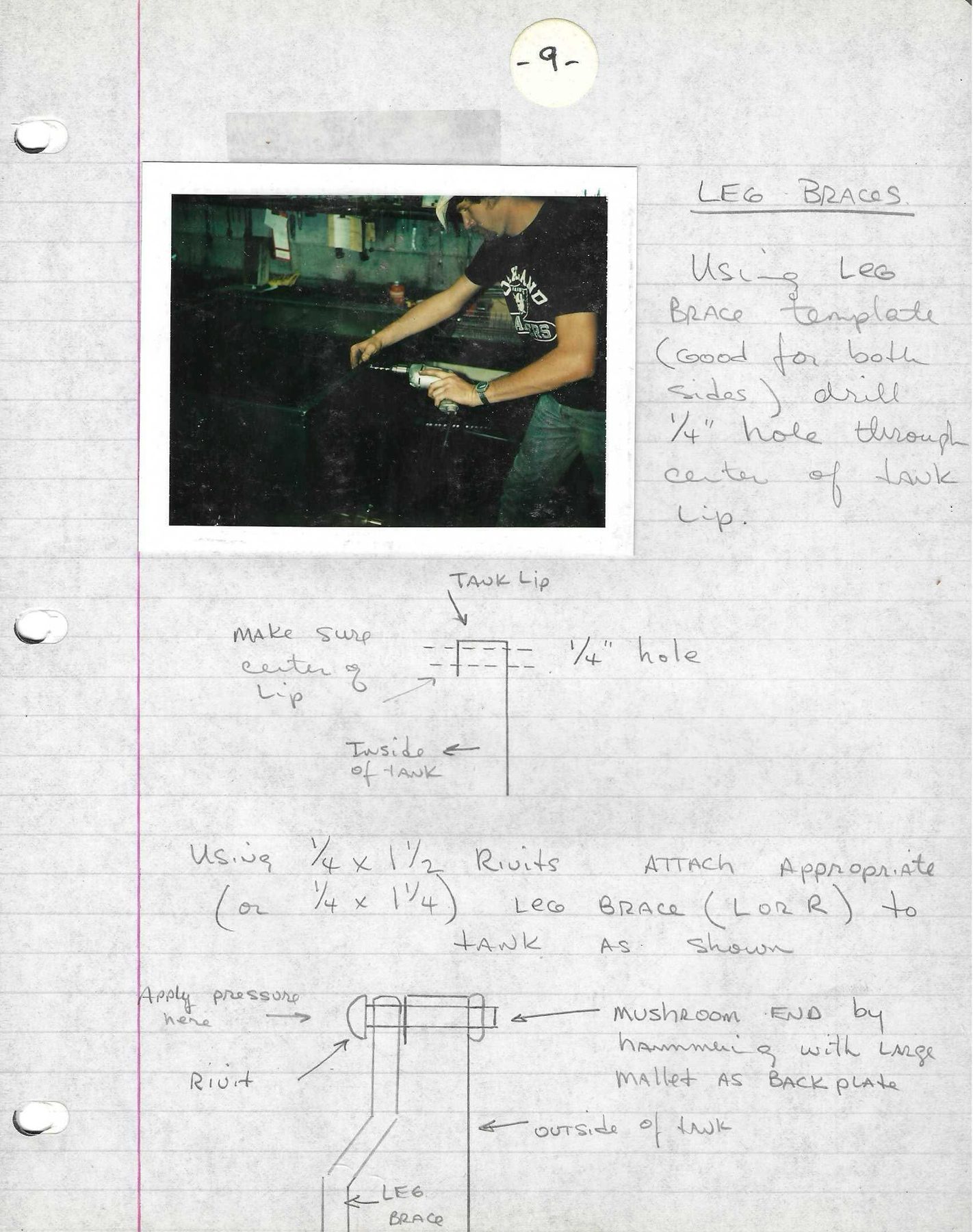
Heading: LEG BRACES.
Using LEG BRACE template (good for both sides) drill 1/4" hole through center of tank Lip.
Photo: A young man (cap, "Oakland Raiders" T-shirt, wristwatch) bending over the tank, drilling with an electric hand drill into the top lip of the tank side, holding a template. Scale reference: the man's forearm/hand vs the tank lip — tank top lip is about at the man's waist-to-chest height while he stands (estimate ~3.5–4 ft above floor, though the tank may be on a work stand).
Sketch 1: Cross-section of the tank wall top: vertical line ("Inside of tank" to the left, arrow), with an outward-folded lip at the top labeled "TANK Lip"; dashed lines through the lip labeled "1/4" hole"; note "MAKE SURE center of Lip".
Using 1/4 x 1 1/2 Rivits ATTACH Appropriate (or 1/4 x 1 1/4) LEG BRACE (L or R) to tank AS Shown
Sketch 2: The lip seen in section with a rivet passing horizontally through lip and leg-brace top; rivet head at left labeled "Rivit", "Apply pressure here →"; right end labeled "MUSHROOM END by hammering with Large Mallet AS BACKplate"; "← outside of tank"; the leg brace runs downward from the lip, jogs (angled offset) and continues down, labeled "LEG BRACE".
Page 10 of 12
(sticker "-10-")
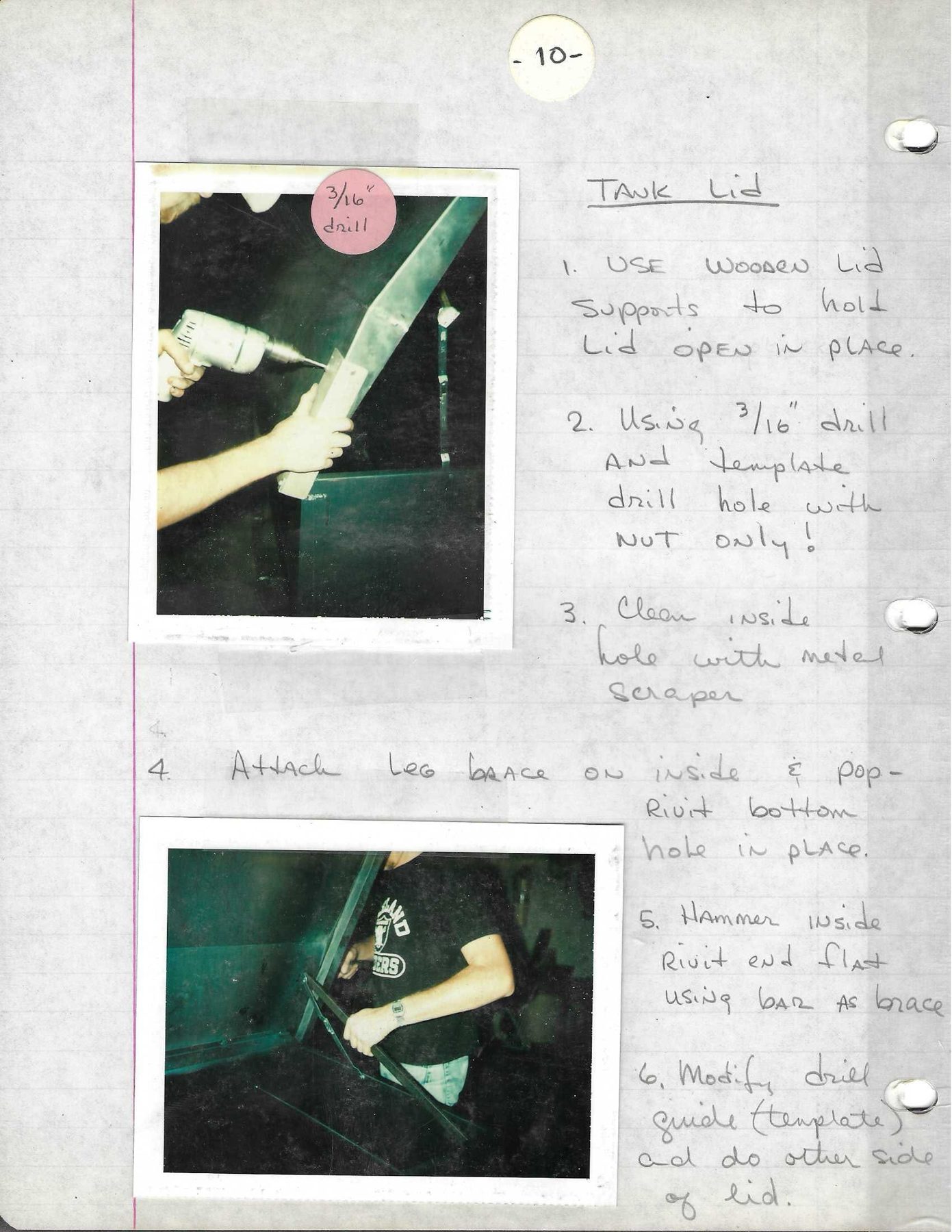
Heading: TANK Lid
- USE WOODEN Lid Supports to hold Lid OPEN in place.
- Using 3/16" drill AND template drill hole with NUT only!
- Clean inside hole with metal scraper
- Attach Leg brace on inside & pop-Rivit bottom hole in place.
- Hammer inside Rivit end flat using bar AS brace
- Modify drill guide (template) and do other side of lid.
Photo 1, sticker "3/16" drill": Close-up: hands holding an electric drill and a flat steel template against a long flat steel strap (the lid "leg brace"/stay) running diagonally upward from the tank side; the open lid edge and the tank's top corner visible. Note: here the "leg brace" is evidently the lid support stay (strap connecting lid to tank side) — the term is used on both p.9 and p.10.
Photo 2: The same young man (Raiders T-shirt, watch) inside/at the open tank, holding a long steel bar braced against the inside of a strap riveted to the tank wall, the open lid rising diagonally behind.
Page 11 of 12
(no number sticker; right edge of page cut off in scan)
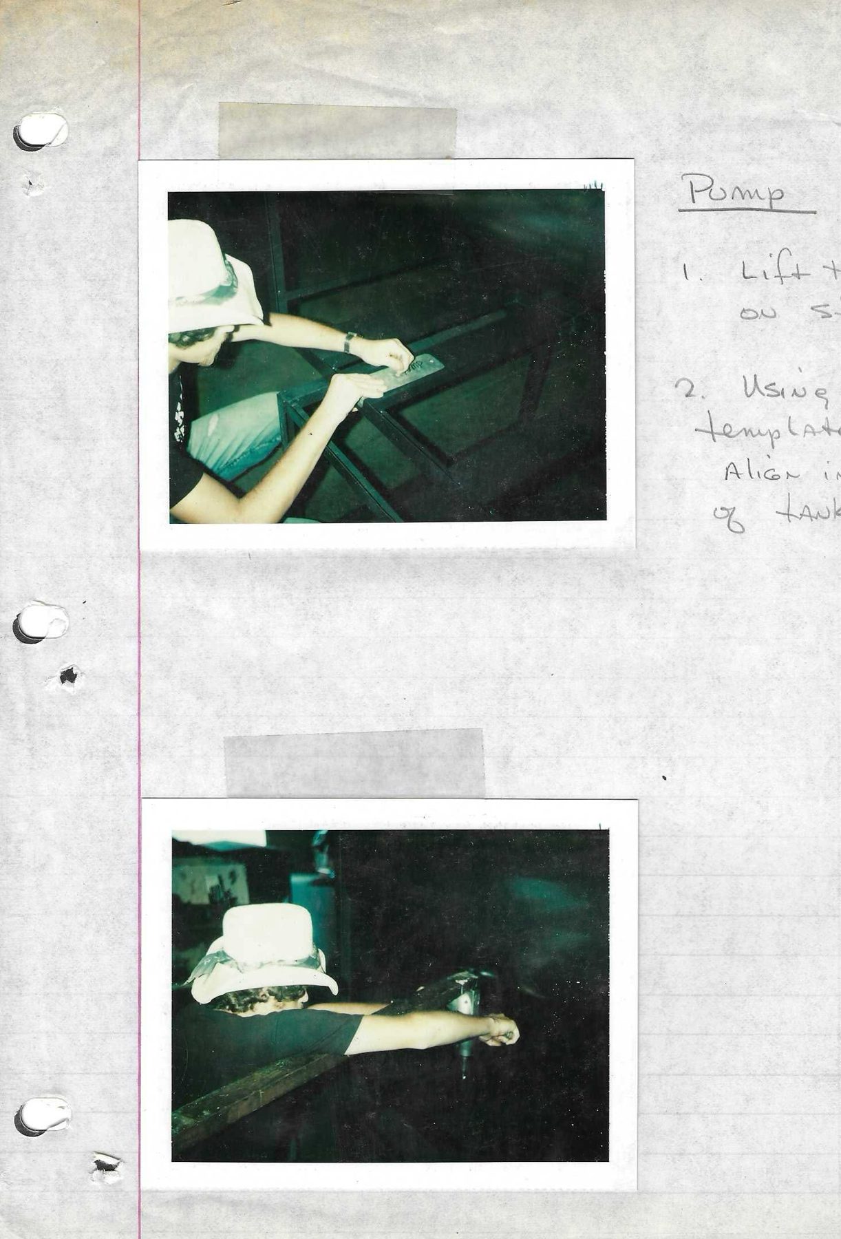
Heading: Pump
- Lift t[…] on s[…] (right side cut off — possibly "Lift tank on stand")
- Using […] template[…] Align i[n…] of tank[…] (cut off)
Photo 1 (top): Young man (light bucket hat, wristwatch, ripped jeans) placing a flat steel template (marked "PUMP" [?]) on the frame's horizontal angle-iron cross members under/inside the stand, positioning holes for the pump mounting.
Photo 2 (bottom): Same man, bent down, drilling (or bolting) into the frame angle iron with an electric drill, under the tank.
Page 12 of 12
(no number sticker)
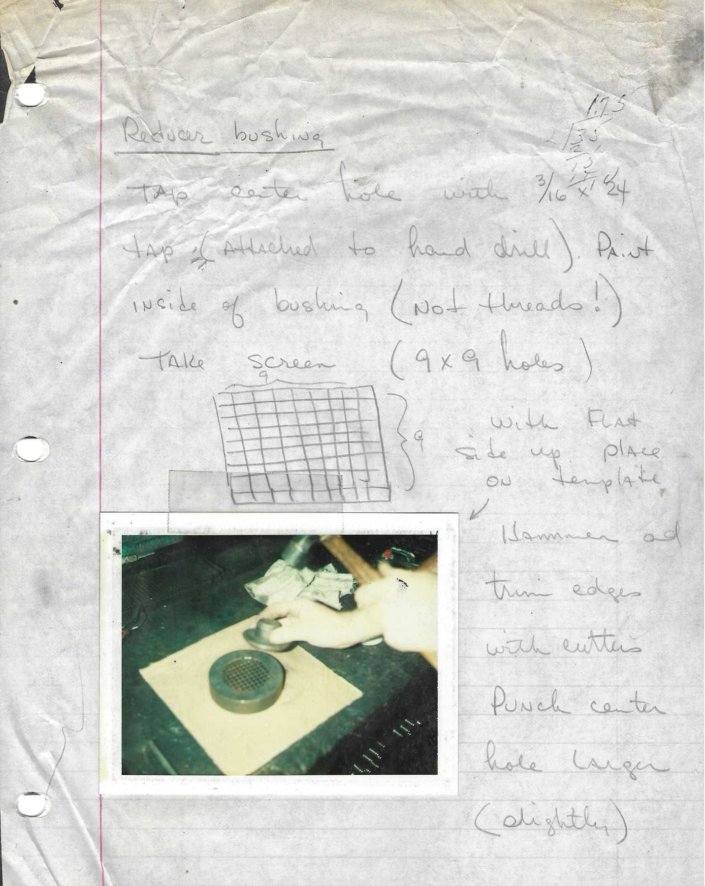
Heading: Reducer bushing
TAP center hole with 3/16 [corrected/overwritten — reads as "1/4"? with "24"; possibly "1/4-24" or "3/16 x 24"] tap ([illegible mark] Attached to hand drill). Paint inside of bushing (NOT threads!)
TAKE Screen (9 x 9 holes)
Marginal arithmetic (upper right): "1.75" written over a long division "2 ) 3.5" with partial products — i.e. 3.5 ÷ 2 = 1.75 (context unknown; possibly a diameter/radius calc).
Sketch: A square wire grid labeled "9" across the top (brace) and "9" on the right side (brace) — 9 × 9 open squares.
with FLAT side up place on template
Hammer and trim edges with cutters
Punch center hole Larger (slightly)
Photo: On a beige pad on the workbench: a short cylindrical steel cup (the reducer bushing / outlet strainer cup, about 3–4" diameter estimate relative to the hand) with a fine round wire screen fitted inside it; a hand holding a round punch/forming tool (with a smaller step) about to press a screen disc; a hammer behind.